Hart Scientific 9140 Dry-well Calibrator User’s Guide Rev.
Fluke Corporation, Hart Scientific Division 799 E. Utah Valley Drive • American Fork, UT 84003-9775 • USA Phone: +1.801.763.1600 • Telefax: +1.801.763.1010 E-mail: support@hartscientific.com www.hartscientific.com Subject to change without notice. • Copyright © 2005 • Printed in USA Rev.
Table of Contents 1 Before You Start . . . . . . . . . . . . . . . . . . . . . . . . . . 1 1.1 1.2 Symbols Used . . . . . . . . . . . . . . . . . . . . . . . . . . . . 1 Safety Information . . . . . . . . . . . . . . . . . . . . . . . . . . 2 1.2.1 1.2.2 1.3 WARNINGS . . . . . . . . . . . . . . . . . . . . . . . . . . . . . . . . . . . 2 CAUTIONS . . . . . . . . . . . . . . . . . . . . . . . . . . . . . . . . . . . 4 Authorized Service Centers. . . . . . . . . . . . . . . . . . . . . .
7.2 Temperature Set-point . . . . . . . . . . . . . . . . . . . . . . . . 21 7.2.1 7.2.2 7.2.3 7.3 Scan . . . . . . . . . . . . . . . . . . . . . . . . . . . . . . . . . 24 7.3.1 7.3.2 7.4 Hold Temperature Display Mode Setting . . . . . . . Switch Wiring . . . . . . . Switch Test Example . . . . . . . . . . . . . . . . . . . . . . . . . . . . . . . . . . . . . . . . . . . . . . . . . . . . . . . . . . . . . . . . . . . . . . . . . . . . . . . . . . . . . . . . . . . . . . . . .
10 Calibration Procedure . . . . . . . . . . . . . . . . . . . . . . 43 10.1 Calibration Points . . . . . . . . . . . . . . . . . . . . . . . . . . 43 10.2 Calibration Procedure . . . . . . . . . . . . . . . . . . . . . . . . 43 10.2.1 10.2.2 10.2.3 Compute DELTA: . . . . . . . . . . . . . . . . . . . . . . . . . . . . . . . . 43 Compute R & ALPHA: . . . . . . . . . . . . . . . . . . . . . . . . . . . . . 44 Accuracy & Repeatability. . . . . . . . . . . . . . . . . . . . . . . . . . . .
Figures Figure 1 Figure 2 Figure 3 Figure 4 Figure 5 Figure 6 Figure 7 Figure 8 iv 9140 Back Panel . . . . . . . . . . . . . . . . . . . . . . . . . . . 9140 Front Panel . . . . . . . . . . . . . . . . . . . . . . . . . . . Inserts available for the 9140 block assembly . . . . . . . . . . . . Controller Operation Flowchart . . . . . . . . . . . . . . . . . . . Well temperature fluctuation at various proportional band settings . Serial Cable Wiring . . . . . . . . . . . . . . . . . . . . . . . . .
Tables Table 1 Table 2 Table 3 International Electrical Symbols . . . . . . . . . . . . . . . . . . . . . 1 9140 controller communications commands. . . . . . . . . . . . . . . 36 9140 controller communications commands continued . . . . . . . . .
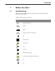
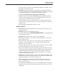
1 Before You Start Symbols Used 1 1.1 Before You Start Symbols Used Table 1 lists the symbols used on the instrument or in this manual and the meaning of each symbol.
140 Dry-well Calibrator User’s Guide Symbol Description Canadian Standards Association OVERVOLTAGE (Installation) CATEGORY II, Pollution Degree 2 per IEC1010-1 refers to the level of Impulse Withstand Voltage protection provided. Equipment of OVERVOLTAGE CATEGORY II is energy-consuming equipment to be supplied from the fixed installation. Examples include household, office, and laboratory appliances.
1 Before You Start Safety Information ing power such as storage in a low humidity temperature chamber operating at 50°C for 4 hours or more. • DO NOT use this instrument for any application other than calibration work. The instrument was designed for temperature calibration. Any other use of the instrument may cause unknown hazards to the user. • Completely unattended operation is not recommended. • Overhead clearance is required. DO NOT place the instrument under a cabinet or other structure.
9140 Dry-well Calibrator User’s Guide ELECTRICAL SHOCK • These guidelines must be followed to ensure that the safety mechanisms in this instrument will operate properly. This instrument must be plugged into a 115 VAC, 60Hz (230 VAC, 50Hz optional), AC only electric outlet. The power cord of the instrument is equipped with a three-pronged grounding plug for your protection against electrical shock hazards. It must be plugged directly into a properly grounded three-prong receptacle.
1 Before You Start Authorized Service Centers • The instrument and any thermometer probes used with it are sensitive instruments that can be easily damaged. Always handle these devices with care. DO NOT allow them to be dropped, struck, stressed, or overheated. • The Factory Reset Sequence (see Section 12.1, Troubleshooting) should be performed only by authorized personnel if no other action is successful in correcting a malfunction.
9140 Dry-well Calibrator User’s Guide Science Park Eindhoven 5108 5692 EC Son NETHERLANDS Phone: +31-402-675300 Telefax: +31-402-675321 E-mail: ServiceDesk@fluke.nl Fluke Int'l Corporation Service Center - Instrimpex Room 2301 Sciteck Tower 22 Jianguomenwai Dajie Chao Yang District Beijing 100004, PRC CHINA Phone: +86-10-6-512-3436 Telefax: +86-10-6-512-3437 E-mail: xingye.han@fluke.com.cn Fluke South East Asia Pte Ltd.
2 Introduction 2 Introduction The Hart Scientific 9140 Mid-Range Field Calibrator may be used as a portable instrument or bench top temperature calibrator for calibrating thermocouple and RTD temperature probes. The 9140 is small enough to use in the field, and accurate enough to use in the lab.
3 Specifications and Environmental Conditions Specifications 3 3.1 Specifications and Environmental Conditions Specifications The following table lists the specifications for this instrument. Accuracy specifications are applicable for a one-year calibration interval. In line with normal prudent metrology practices, Hart Scientific recommends a short-cycle interval of six months for new units during the first year. 3.2 Power 115 VAC (±10%), 4.4 A or 230 VAC (±10%), 2.
9140 Dry-well Calibrator User’s Guide operated in an excessively dusty or dirty environment. Maintenance and cleaning recommendations can be found in the Maintenance Section of this manual.
4 Quick Start Unpacking 4 4.1 Quick Start Unpacking Unpack the dry-well carefully and inspect it for any damage that may have occurred during shipment. If there is shipping damage, notify the carrier immediately. Verify that the following components are present: • 9140 Dry-well • Insert • Insert Removal Tool • Power Cord • Serial Cable • User's Guide • 9930 Software Package 4.2 Set-Up Place the calibrator on a flat surface with at least 6 inches of free space around the instrument.
9140 Dry-well Calibrator User’s Guide dry-well will turn on and begin to heat to the previously programmed temperature set-point. The front panel LED display will indicate the actual dry-well temperature. 4.4 Setting the Temperature Section 7.2 explains in detail how to set the temperature set-point on the calibrator using the front panel keys. The procedure is summarized here. (1) Press “SET” twice to access the set-point value. (2) Press “UP” or “DOWN” to change the set-point value.
5 Parts and Controls Rear Panel 5 Parts and Controls The user should become familiar with the dry-well calibrator and its parts: 5.1 Rear Panel Figure 1 on page 13. Power Cord - At the rear of the calibrator is the removable power cord inlet that plugs into an IEC grounded socket. Power Switch - The power switch is located on the power entry module (PEM). The PEM also houses the fuses and the dual voltage selector.
9140 Dry-well Calibrator User’s Guide around the two corners of the calibrator are provided for airflow. The area around the calibrator must be kept clear to allow adequate ventilation. The airflow is directed upward and as a result, can be extremely hot. 5.2 Front Panel Figure 2 on page 14. Controller Display - The digital display is an important part of the temperature controller because it not only displays set and actual temperatures but also various calibrator functions, settings, and constants.
5 Parts and Controls Constant Temperature Block Assembly EXIT – Used to exit a function and to skip to the next function. Any changes made to the displayed value are ignored. 5.3 Constant Temperature Block Assembly Figure 3 on page 15. 5.3.1 Constant Temperature Block The “Block” is made of aluminum and provides a relatively constant and accurate temperature environment in which the sensor that is to be calibrated is inserted. A 1.
9140 Dry-well Calibrator User’s Guide • Insert D (comparison block): 2 each at 3 mm, 4 mm, and 6 mm 16
6 General Operation Calibrator Set-Up 6 6.1 General Operation Calibrator Set-Up Place the calibrator on a flat surface with at least 6 inches of free space around the instrument. Overhead clearance is required. DO NOT place under a cabinet or other structure.Plug the power cord into a grounded mains outlet. Observe that the nominal voltage corresponds to that indicated on the back of the calibrator. Gently insert the probe sleeve into the well.
9140 Dry-well Calibrator User’s Guide • Using the same straight slot screwdriver, move the heater switch to display “230V”. See the rear panel drawing in Figure 1 on page 13. NOTE: If the heater switch and the fuse holder do not both read 230V when complete, the unit will either not heat or only heat at a fraction of its capacity. If not done properly, the unit could become damaged and void the calibration and warranty. CAUTION: DO NOT plug the unit into 230 V if the heater switch and fuse holder read 115.
6 General Operation Calibrating Probes Using the same hole for the reference thermometer and the test probe may have better results. This however requires switching the probes which takes more time. One must allow a few minutes after inserting the probes for the temperature to stabilize before making measurements. Because of temperature variations along the length of the well, best results are obtained when comparing probes of similar construction and inserting them the same depth into the well.
7 Controller Operation Well Temperature 7 Controller Operation This chapter discusses in detail how to operate the dry-well temperature controller using the front control panel. Using the front panel key-switches and LED display the user may monitor the well temperature, set the temperature set-point in degrees C or F, monitor the heater output power, adjust the controller proportional band, and program the calibration parameters, operating parameters, and serial interface configuration.
9140 Dry-well Calibrator User’s Guide Figure 4 Controller Operation Flowchart 22
7 Controller Operation Temperature Set-point 100.0 C S Well temperature in degrees Celsius Access set-point memory 1. 100. Set-point memory 1, 100°C currently used To change to another set-point memory press “UP” or “DOWN”. 4. 300. New set-point memory 4, 300°C Press “SET” to accept the new selection and access the set-point value. S 7.2.2 Accept selected set-point memory Set-point Value The set-point value may be adjusted after selecting the set-point memory and pressing “SET”. 4. 200.
9140 Dry-well Calibrator User’s Guide Un= F 7.3 New units selected Scan The scan rate can be set and enabled so that when the set-point is changed the dry-well heats or cools at a specified rate (degrees per minute) until it reaches the new set-point. With the scan disabled the dry-well heats or cools at the maximum possible rate. 7.3.1 Scan Control The scan is controlled with the scan on/off function that appears in the main menu after the temperature scale units.
7 Controller Operation Temperature Display Hold 7.4 Temperature Display Hold The 9140 has a display hold function which allows action of an external switch to freeze the displayed temperature and stop the set-point from scanning. This is useful for testing thermal switches and cutouts. This section explains the functions available for operating the temperature hold feature. An example follows showing how to set up and use the hold feature to test a switch. 7.4.
9140 Dry-well Calibrator User’s Guide sistor. The calibrator measures the voltage at the red terminal and interprets +5V as open and 0V as closed. 7.4.4 Switch Test Example This section describes a possible application for the temperature hold feature and how the instrument is set up and operated. Suppose you have a thermal switch which is supposed to open at about 75°C and close at about 50°C and you want to test the switch to see how accurate and repeatable it is.
7 Controller Operation Secondary Menu is. With good control stability the percent heating power should not fluctuate more than ±1% within one minute. The heater power display is accessed in the secondary menu. Press “SET” and “EXIT” simultaneously and release. The heater power will be displayed as a percentage of full power. 100.0 C S+ E SEC 12.
9140 Dry-well Calibrator User’s Guide The temperature stability of the well and response time depend on the width of the proportional band. If the band is too wide the well temperature will deviate excessively from the set-point due to varying external conditions. This is because the power output changes very little with temperature and the controller cannot respond very well to changing conditions or noise in the system.
7 Controller Operation Controller Configuration 7.6 Controller Configuration The controller has a number of configuration and operating options and calibration parameters which are programmable via the front panel. These are accessed from the secondary menu after the proportional band function by pressing “SET”. Pressing “SET” again enters the first of three sets of configuration parameters — calibration parameters, operating parameters and serial interface parameters.
9140 Dry-well Calibrator User’s Guide 7.6.1.2 ALPHA This probe parameter refers to the average sensitivity of the probe between 0 and 100°C. The value of this parameter is set at the factory for best instrument accuracy. 7.6.1.3 DELTA This probe parameter characterizes the curvature of the resistance-temperature relationship of the sensor. The value of this parameter is set at the factory for best instrument accuracy. 7.
7 Controller Operation Serial Interface Parameters 4800 b New baud rate Press “SET” to set the baud rate to the new value or “EXIT” to abort the operation and skip to the next parameter in the menu. 7.8.1 Sample Period The sample period is the next parameter in the serial interface parameter menu. The sample period is the time period in seconds between temperature measurements transmitted from the serial interface.
9140 Dry-well Calibrator User’s Guide 7.8.1.2 Linefeed The final parameter in the serial interface menu is the linefeed mode. This parameter enables (on) or disables (off) transmission of a linefeed character (LF, ASCII 10) after transmission of any carriage-return. The linefeed parameter is indicated by, LF Serial linefeed parameter Press “SET” to access the linefeed parameter. LF= On Current linefeed setting The mode may be changed using “UP” or “DOWN” and pressing “SET”.
8 Digital Communication Interface Serial Communications 8 Digital Communication Interface The dry-well calibrator is capable of communicating with and being controlled by other equipment through the digital serial interface. With a digital interface the instrument may be connected to a computer or other equipment. This allows the user to set the set-point temperature, monitor the temperature, and access any of the other controller functions, all using remote communications equipment.
9140 Dry-well Calibrator User’s Guide rial interface parameters menu are the BAUD rate, the sample rate, the duplex mode, and the linefeed parameter. 8.1.2.1 Baud Rate The baud rate is the first parameter in the menu. The display will prompt with the baud rate parameter by showing “BAUd”. Press “SET” to choose to set the baud rate. The current baud rate value will then be displayed. The baud rate of the 9140 serial communications may be programmed to 300, 600, 1200, 2400, 4800, or 9600 baud.
8 Digital Communication Interface Interface Commands face commands are discussed in Section. All commands are ASCII character strings terminated with a carriage-return character (CR, ASCII 13). 8.2 Interface Commands The various commands for accessing the calibrator functions via the digital interfaces are listed in this section (see Table 2). These commands are used with the RS-232 serial interface. The commands are terminated with a carriage-return character.
9140 Dry-well Calibrator User’s Guide Table 2 9140 controller communications commands Command Description Command Format Command Example Returned Returned Example set: 9999.99 {C or F} set: 150.00 C Acceptable Values Display Temperature Read current set-point s[etpoint] s Set current set-point to n s[etpoint]=n s=350 Instrument Range Read temperature t[emperature] t t: 9999.9 {C or F} t: 55.
8 Digital Communication Interface Interface Commands Table 3 9140 controller communications commands continued Command Description Command Format Set serial linefeed mode: lf[eed]=on/of[f] Command Example Returned Returned Example Acceptable Values ON or OFF Set serial linefeed mode to on lf[eed]=on lf=on Set serial linefeed mode to off lf[eed]=of[f] lf=of Miscellaneous Other Commands Read firmware version number *ver[sion] *ver ver.9999,9.
9 Test Probe Calibration Comparison Methods 9 Test Probe Calibration For optimum accuracy and stability, allow the calibrator to warm up for 10 minutes after power-up and then allow adequate stabilization time after reaching the set-point temperature. After completing operation of the calibrator, allow the well to cool by setting the temperature to 100°C for one-half hour before switching the power off. 9.1 Comparison Methods For information on automating your testing, contact Hart Scientific. 9.1.
9140 Dry-well Calibrator User’s Guide 2. Place the probe to be calibrated, the unit under test (UUT), in another well. 3. With the reference inserted into one well and the probe under test inserted into a second well, make measurements of each. 4. Swap the locations of the reference probe and probe under test. Allow plenty of time for thermal settling. 5. Make another set of measurements of the reference probe and the probe under test. 6. Average the two measurements of the reference probe.
9 Test Probe Calibration Dry-well Characteristics WARNING: DO NOT remove inserts when heating or when the unit is hot. Stabilization and Accuracy The stabilization time of the dry-well calibrator will depend on the conditions and temperatures involved. Typically the test well will be stable to 0.1°C within 5 minutes of reaching the set-point temperature as indicated by the display.
9140 Dry-well Calibrator User’s Guide timate stability will be achieved 10 to 20 minutes after reaching the set temperature. Inserting a cold probe into a well will require another period of stabilizing depending on the magnitude of the disturbance and the required accuracy. For example, inserting a .25 inch diameter room temperature probe into a sleeve at 300°C will take 5 minutes to be within 0.1°C of its settled point and will take 10 minutes to achieve maximum stability.
10 Calibration Procedure Calibration Points 10 Calibration Procedure Sometimes the user may want to calibrate the dry-well to improve the temperature set-point accuracy. Calibration is done by adjusting the controller probe calibration constants R0 , ALPHA, and DELTA so that the temperature of the dry-well as measured with a standard thermometer agrees more closely with the set-point.
9140 Dry-well Calibrator User’s Guide T ⎤ ⎡ T ⎤⎡ T ⎤ ⎡ T ⎤⎡ C = ⎢ 3 ⎥⎢1 − 3 ⎥ − ⎢ 2 ⎥⎢1 − 2 ⎥ ⎣100 ⎦⎣ 100 ⎦ ⎣100 ⎦⎣ 100 ⎦ T ⎤ ⎡ T ⎤⎡ T ⎤ ⎡ T ⎤⎡ D = ⎢ 2 ⎥⎢1 − 2 ⎥ − ⎢ 1 ⎥⎢1 − 1 ⎥ ⎣100 ⎦⎣ 100 ⎦ ⎣100 ⎦⎣ 100 ⎦ E = R3 − R2 F = R2 − R1 delta = AF − BE DE − CF T1-3 - Measured temperature using thermometer. R1-3 - Value of set-point resistance from display of 9140. (Press SET and DOWN at the same time.) where T1 and R1 are the measured temperature and resistance at 50.
10 Calibration Procedure Calibration Procedure b. Press SET then use the UP or DOWN keys until the correct numerical setting is displayed. Press SET to accept the new value. c. Repeat step b. for ALPHA and DELTA. 10.2.3 Accuracy & Repeatability 1. Check the accuracy of the dry-well at various points over the calibration range. 2. If dry-well does not pass specification at all set-points, repeat Calibration Procedure.
11 Maintenance 11 Maintenance • The calibration instrument has been designed with the utmost care. Ease of operation and simplicity of maintenance have been a central theme in the product development. Therefore, with proper care the instrument should require very little maintenance. Avoid operating the instrument in an oily, wet, dirty, or dusty environment. • If the outside of the instrument becomes soiled, it may be wiped clean with a damp cloth and mild detergent.
12 Troubleshooting Troubleshooting Problems, Possible Causes, and Solutions 12 Troubleshooting If problems arise while operating the 9140, this section provides some suggestions that may help you solve the problem. A wiring diagram is also included. 12.1 Troubleshooting Problems, Possible Causes, and Solutions In the event that the instrument appears to function abnormally, this section may help to find and solve the problem.
9140 Dry-well Calibrator User’s Guide Problem Possible Causes and Solutions The display shows an error code Controller problem. The error messages signify the following problems with the controller. Err 1 - a RAM error Err 2 - a NVRAM error Err 3 - a Structure error Err 4 - an ADC setup error Err 5 - an ADC ready error Err 6 – a defective control sensor Err 7 – a heater error Initialize the system by performing the Factory Reset Sequence describe above.