
Application Note


2 Fluke Corporation Stepping up to power quality tools
Take a general power survey
Unless you already suspect the cause of the
power quality problem, a good place to start is
by performing a general power quality survey.
Begin as far back toward the service entrance in
the distribution system as possible. For example,
most commercial buildings utilize a 208Y/120 volt
distribution system. So, begin measurements at
the first panel board downstream of the 208Y/120
volt transformers. This is where you will find the
feeders and branch circuits supplying single-
phase loads for the facility. Should possible power
quality issues be identified, it will be necessary to
drill down further into the distribution system to
isolate the problem-causing equipment.
If you know where in the distribution system
the problems occur, then start at that location and
work back upstream in the distribution system.
For example, a programmable logic controller
(PLC) intermittently gives over temperature alarms
for the system it is controlling. However, inves-
tigations reveal no over-temperature problems
exists in the process system. It is reasonable to
expect a power quality issue occurring intermit-
tently at the plc supply as one possible cause of
the false alarms. Therefore, begin measurements
and recordings at the 120 volt supply to the plc,
checking for a power quality issue. If a power
quality problem is found, go back to the panel
board supplying the plc branch circuit and begin
investigating other loads on the panel board. If
one particular load is suspected of causing the
problem, then it will be easy enough to check
values on that specific piece of equipment as it
runs through its operational cycle.
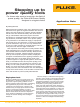
The first screen of the power quality analyzer shows how to connect
the test leads to the instrument.
The first screen of the power quality
analyzer
The first screen to appear when you turn on the
analyzer shows how to connect the test leads to
the instrument. Should any instrument adjust-
ments need to be made, pressing the menu key
and opening the “instrument setup” screen
provides a menu of possible changes. Such
adjustments include changing the specific type
of probes being used, the harmonic values to be
measured, the date and time, and other basic
parameters.
Connect the red
test lead to the ter-
minal marked “1”
Connect the black
test lead to the
terminal marked
“COM”
Connect the cur-
rent clamp to the
terminal marked
“2”