
User Manual
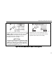
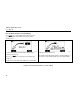

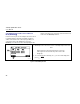
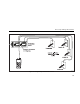


Table Of Contents
- CableIQ™ Qualification Tester Users Manual
- LIMITED WARRANTY AND LIMITATION OF LIABILITY
- Table of Contents
- List of Figures
- List of Tables
- Overview of Features
- Registration
- Contacting Fluke Networks
- Additional Resources for Cable Testing Information
- Unpacking
- Symbols and Safety Information
- Physical Features
- Using the Wiremap Adapter and Remote ID Locators
- Powering the Tester
- Verifying Operation
- Setting User Preferences
- Checking the Hardware and Software Versions
- Qualifying Cabling with the Autotest
- Discovering Cabling Characteristics
- Using the Toner
- Using the IntelliTone Cable Map Function
- Blinking a Port Light
- Testing for Continuity
- Using the Continuity Toner
- Locating Crosstalk and Impedance Faults on Twisted Pair Cabling
- Testing Speaker Cabling
- Calibrating Length Measurements
- Memory Functions
- Maintenance
- If Something Seems Wrong
- Options and Accessories
- Specifications
- Appendix A: Diagnosing Cabling Faults
- Index

Discovering Cabling Characteristics
41
avv02.bmp avv60.bmp
The tester is connected to an active telephone circuit. R1,
T1, R2, and T2 show connections for lines 1 and 2. For
active digital lines, the length shown may fluctuate or
may not be shown (
−−−) because of varying
termination on the line. See page 6.
W
arning
Thetesterisnotintendedtobeconnectedtoactive
telephoneinputs,systems,orequipment,including
ISDNdevices.Exposuretothevoltagesappliedby
theseinterfacesmaydamagethetesterandcreate
apotentialshockhazardfortheuser.
Short between pins 1 and 2. Cable length is 92 m.
Shorts are shown near the bottom of the wire map
regardless of their location on the cabling.
Figure15.DiscoverModeResultsforTwistedPairCabling(cont.)