
User's Manual

1750
Operators Manual
14
• End of recording session
You can re-verify if desired, correctness of live data and then download data,
power off the Recorder, and pack up fir transport.
Installing the Recorder
To install the Recorder at a facility, follow the basic steps below.
1. Position the Recorder within 2.5 m (8 ft) of the monitoring location.
2. The Recorder can be set on the floor or a table, or attached and secured to a pole
or other mounting surface.
3. Connect the Recorder to a 100 to 240 V ac power source.
• Connect the power cord to the Recorder using the appropriate supplied
adapter.
• Connect the power cord to a properly grounded wall outlet.
WCaution
Be sure to plug the power cord into the Recorder panel
BEFORE connecting it to an outlet
4. Plug the power cord into a properly grounded wall outlet.
5. Turn on the PDA and tap the Power View icon
to launch Power View.
6. If a Recorder is within range and is not password protected, the Home screen for
live data appears.
7. If more than one Recorder is within range, select one Recorder for use.
8. If you have established password protection, you must type the correct password
in the Password text box and tap the Enter button. (Password protection is
established for a specific Recorder using either the Setup Password menu in
Power View or the Power Analyze software).
9. All LEDs should flash ON, then OFF, and then each should turn ON and OFF in
sequence. The LEDs will then remain on if you make a secure connection and
there is sufficient voltage and current.
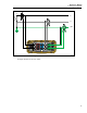
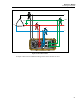
Connecting the Recorder to the Wiring
After you have set up the Recorder you are ready to connect the clamps and probes to the
wiring. Refer to the Power Type diagrams provided on the PDA or in the 1750 Operators
Manual.
In most cases, you should install the current clamps first. Because they are clamped
around wires, current clamps are usually more secure than voltage probes. Examine the
conductors you are about to connect to and determine if you should attach the current
clamps to the phase wires before you connect the voltage probes.
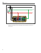
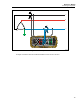
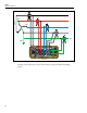
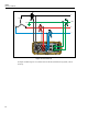
1. Select and attach the appropriate current clamps to the Recorder.
2. Select and attach the appropriate voltage probes to the Recorder.
Note
If your power connections require potential transformers (PTs) or current
transformers (CTs), you can use the ratio settings in Power View to set the
Recorder to display readings as they exist on the primary side of the PT and
CT (for example, 12000 V).