
User's Manual

805/805 FC
Users Manual
6
Controls and Connections
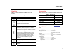
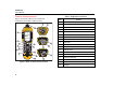
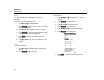
Figure 1 shows the location of the controls and
connections for the Meter. Table 3 is a key.
1
2
3
4
5
7
8
9
10
11
12
15
18
17
14
13
14
13
6
16
gqi01.eps
Figure 1. Meter Controls and Connections
Table 3. Keypad and Connectors
Item Control
LCD
Power on/off
Measure
Navigation
Enter
Save
Setup
Connector cover
Status LED
Memory
Flashlight on/off
Backlight on/off
USB port
External sensor port
Audio port (805 only)
Vibration sensor
IR temperature sensor
Flashlight