
User manual


Input and Channel Configuration
Channel Configuration 3
3-7
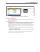
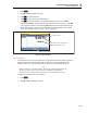
Channel List
Slot 1
Slot 2
Empty
Module Installed
Slot 3
Empty
hce031.eps
Figure 3-3. Module Indicator (Input Module Installed Shown)
Channel Configuration
This section contains instructions on how to configure the channels after the inputs are
connected to the Input Module.
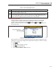
About Channel Numbers
A channel number (Ch) is a numerical identification associated with a set of terminals on
the Input Module. The channel number of the input is determined by the slot number the
Input Module is in (1, 2, or 3) followed by the number of the terminal the input is
connected to (1 to 22) as illustrated in Figure 3-4. The front-panel inputs are permanently
assigned to channel Ch001. Here are some examples on how to determine the channel
number of an input:
• A voltage source is connected to input terminal 4 (04) in the Input Module and then
slid into slot 1. The channel is Ch104.
• A thermistor source is connected to input terminal 8 (08) in the Input Module and then
slid into slot 2. The channel is Ch208.
• A voltage source is connected to the front-panel terminals. The channel is Ch001.
Table 3-2 shows channel types and channel numbers.