
User manual
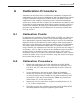
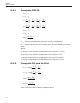
Table Of Contents
- Table of Contents
- 1 Before You Start 1
- 2 Introduction 7
- 3 Specifications and Environment Conditions 9
- 4 Quick Start 13
- 5 Parts and Controls 15
- 6 General Operation 17
- 7 Controller Operation 19
- 7.1 Target Temperature 19
- 7.2 Temperature Set-point 19
- 7.3 Temperature Scale Units 21
- 7.4 Scan 22
- 7.5 Set-point Resistance 23
- 7.6 Temperature Scale Units 23
- 7.7 Secondary Menu 23
- 7.8 Heater Power 23
- 7.9 Proportional Band 24
- 7.10 Controller Configuration 25
- 7.11 Operating Parameters 25
- 7.12 Serial Interface Parameters 26
- 7.13 Calibration Parameters 27
- 8 Digital Communication Interface 29
- 9 Calibration Procedure 35
- 10 Maintenance 39
- 11 Troubleshooting 41
- Figures
- Tables

9.2.3 Compute BETA
x
T
=
⎡
⎣
⎢
⎤
⎦
⎥
−
1
100
1
y
T
=
⎡
⎣
⎢
⎤
⎦
⎥
1
100
()()
()
()
()
()()
()
beta
alpha x y
T
xy
delta
y
R
r
alpha x y
=+−−
1
3
1
3
2
1
0
3
Where T
1
and R
1
are the measured temperature and resistance at –25.00°C
and alpha, rzero, and delta are the new values of ALPHA, R0, and DELTA
calculated above.
Program the new values for R0 (rzero), ALPHA (alpha), DELTA (delta), and
BETA (beta) into the instrument with the following steps.
1. Reference Section 7.13 to display R0.
2. Press the “SET” button then use the “UP” or “DOWN” buttons until
the correct numerical setting is displayed. Press the “SET” button to
accept the new value.
3. Repeat step 2 for ALPHA, DELTA, and BETA.
9.2.4 Accuracy and Repeatability
Check the accuracy of the instrument at various points over the calibrated
range. If the instrument does not pass specification at all set-points, repeat
the Calibration Procedure.
37
9
Calibration Procedure