
User manual
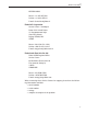
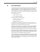
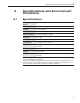
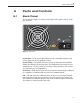
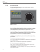
Table Of Contents
- Table of Contents
- 1 Before You Start 1
- 2 Introduction 7
- 3 Specifications and Environment Conditions 9
- 4 Quick Start 13
- 5 Parts and Controls 15
- 6 General Operation 17
- 7 Controller Operation 19
- 7.1 Target Temperature 19
- 7.2 Temperature Set-point 19
- 7.3 Temperature Scale Units 21
- 7.4 Scan 22
- 7.5 Set-point Resistance 23
- 7.6 Temperature Scale Units 23
- 7.7 Secondary Menu 23
- 7.8 Heater Power 23
- 7.9 Proportional Band 24
- 7.10 Controller Configuration 25
- 7.11 Operating Parameters 25
- 7.12 Serial Interface Parameters 26
- 7.13 Calibration Parameters 27
- 8 Digital Communication Interface 29
- 9 Calibration Procedure 35
- 10 Maintenance 39
- 11 Troubleshooting 41
- Figures
- Tables

grammed temperature set-point. The front panel LED display indicates the
actual instrument temperature.
4.4 Setting the Temperature
Section 8.2 explains in detail how to set the temperature set-point on the
calibrator using the front panel keys. The procedure is summarized here.
1. Press the “SET” button twice to access the set-point value.
2. Press the “UP” or “DOWN” button to change the set-point value.
3. Press the “SET” button to program in the new set-point.
4. Press the “EXIT” button to return to the temperature display.
When the set-point temperature is changed the controller switches the
heater on or off to raise or lower the temperature. The displayed tempera
-
ture gradually changes until it reaches the set-point temperature. The tar
-
get may require 5 to 10 minutes to reach the set-point depending on the
span. Another 5 to 10 minutes is required to stabilize within ±0.1°Cofthe
set-point. Ultimate stability may take 15 to 20 minutes more of stabilization
time.
9133
User’s Guide
14