
User manual
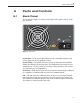
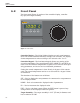
Table Of Contents
- Table of Contents
- 1 Before You Start 1
- 2 Introduction 7
- 3 Specifications and Environment Conditions 9
- 4 Quick Start 13
- 5 Parts and Controls 15
- 6 General Operation 17
- 7 Controller Operation 19
- 7.1 Target Temperature 19
- 7.2 Temperature Set-point 19
- 7.3 Temperature Scale Units 21
- 7.4 Scan 22
- 7.5 Set-point Resistance 23
- 7.6 Temperature Scale Units 23
- 7.7 Secondary Menu 23
- 7.8 Heater Power 23
- 7.9 Proportional Band 24
- 7.10 Controller Configuration 25
- 7.11 Operating Parameters 25
- 7.12 Serial Interface Parameters 26
- 7.13 Calibration Parameters 27
- 8 Digital Communication Interface 29
- 9 Calibration Procedure 35
- 10 Maintenance 39
- 11 Troubleshooting 41
- Figures
- Tables

4 Quick Start
4.1 Unpacking
Unpack the calibrator carefully and inspect it for any damage that may have
occurred during shipment. If there is shipping damage, notify the carrier
immediately.
Verify that the following components are present:
•
9133 calibrator
•
report of calibration
•
power cord
•
user's guide
•
serial cable
•
target cover
•
9930 software
4.2 Set Up
Place the calibrator on a flat surface with at least 6 inches of free space
around the instrument. The prop may be swung down to raise the front of
the instrument from a horizontal position. Plug the power cord into a
grounded mains outlet. Observe that the nominal voltage corresponds to
that indicated on the back of the calibrator.
Turn on the power to the calibrator by toggling the power switch on. The
fan should begin quietly blowing air through the instrument and the con
-
troller display should illuminate after 3 seconds. After a brief self-test the
controller should begin normal operation. If the unit fails to operate please
check the power connection.
The thermal electric devices will start operating to bring the temperature of
the calibrator to the set-point temperature and the display will begin to
show the actual target temperature.
Caution: Use the target cover at temperatures below 5°C. If ice forms on
the target, the IR probe will not indicate the correct temperature.
4.3 Power
Plug the instrument power cord into a mains outlet of the proper voltage,
frequency, and current capability. Refer to Section 3.1, Specifications for
power details. Turn the instrument on using the rear panel “POWER”
switch. The instrument turns on and begins to heat to the previously pro
-
13
4
Quick Start