
User's Guide
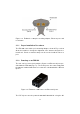
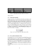
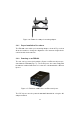
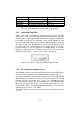
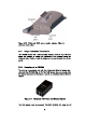
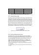
Table Of Contents

LED # (Color) Boot Status Link Quality
1 (Red) Booting core system poor/link absent
2 (Orange) Booting wireless system fair
3 (Green) Booting routing engine good
4 (Green) Booting unit configuration very good
Table 3.1: FM1100 Boot/Link Status LEDs Color Scheme
adapter included.
3.1.3 Status and Link LEDs
A panel on the back of the FM1100, shown in Fig. 3.4, provides seven
(7) LEDs which can be used to check the unit and the link quality status.
From the left-hand side, the first 3 green LEDs indicate the unit power, the
Ethernet port #1 activity and the Ethernet port #2 activity, respectively. The
remaining 4 colored LEDs indicate the level of the link signal and can be
used for antenna alignment purposes. During the unit boot-up process,
the 4 colored LEDs indicate the boot status and can be used for problem
detection. In fact, the LEDs light up in sequence from the leftmost one (red)
to rightmost one (bright green). If the LEDs lighting up sequence does
not complete, then an error has been detected during the booting process.
Please refer to Table 3.1 for details.
Figure 3.4: From left to right status LEDs, link/boot LEDs.
3.1.4 Factory Default Hardware Reset
The FM1100 can be reset to factory default using the RESET button placed
nearby the Ethernet ports as shown in Fig. 3.2. To reset the FM1100 to
factory default settings, power up the unit and wait approximately 40 sec-
onds for the unit to boot up. Once the unit is up and running, press the
reset button for 5 seconds. The FM1100 will restore the factory default set-
tings and automatically reboot. After the reset, the default IP address of
192.168.0.10/255.255.255.0 is restored and the administrator password is
set to admin.
The RESET button can also be used to reboot the unit when pressed for 1
second.
10