
User's Manual

3
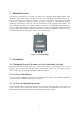
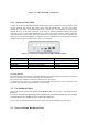
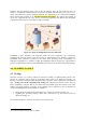
Figure 3.2: FM 4500 MOBI – Bottom view
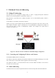
3.1.2 Status and Link LEDs
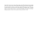
A panel on the front of the FM4500 MOBI, shown in Figure 3.3, provides six (6) LEDs which can be
used to check the unit and the link quality status. From the left-hand side, the first 2 green LEDs
indicate the unit power, the Ethernet port activity, respectively. The remaining 4 colored LEDs
indicate the level of the link signal and can be used for antenna alignment purposes. During the
unit boot-up process, the LEDs indicate the boot status and can be used for problem detection.
Specifically, the 4 colored LEDs light up in sequence from the leftmost one (red) to rightmost one
(bright green). If the LEDs lighting up sequence does not complete, then an error has been detected
during the booting process. Please refer to Table 3.3 for details.
Figure 3.3: From Left To Right Status LEDs, Link/Boot LEDs
LED$#$(Color )
!
Boot$Status
!
Link$ Quality!
1$(Red )
!
"##$%&'!(# )*!+,+$*-
!
.##)/0%&1!23+*&$
!
2$(O ran ge)
!
"##$%&'!4%)*0*++!+,+$*-
!
52%)!
3$(Gre e n)
!
"##$%&'!)#6 $%&'!*&'%&*
!
7##8
!
4$(Gre e n)
!
"##$%&'!6&%$!(#&9%'6)2$%#&
!
:*),!'##8
!
Table 3.3: FM4500 MOBI Boot/Link Status LEDs Color Scheme
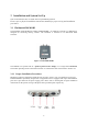
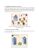
Powering the unit
FM4500 could be powered using a standard IEEE802.3at switch through the LAN1/PoE 8-pins M12
ports, or with a 48Vdc in (not included) using the 5 pins M12 slot.
Please refer to the installation instructions for the specific port wiring.
To minimize power losses, it is recommended to install the PoE injector as close as possible to the
FM radio. The maximum suggested distance is 330ft/ 100m.
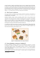
3.2 Use Shielded Cables
Please note that only professional outdoor-rated shielded cables must be used in conjunction with the
FM radios.
In order to secure proper grounding for the radio and to get reliable connectivity, it is strongly
recommended to use shielded CAT5/6 cables and connectors.
Please refer to installation instructions for proper wiring and installation procedures
3.3 Factory Default Hardware Reset