
User's Manual

4
3 Installation and System Set-Up
This section describes how to install and set up Fluidmesh products.
3.1 FM 3500 ENDO
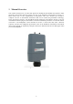
The Fluidmesh 3500 ENDO (part number FM3500E-HW), for simplicity referred to as FM3500
ENDO) is a wireless radio enclosed in an IP66-rated metal enclosure that can be pole or wall
mounted.
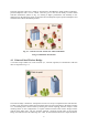
The FM3500 ENDO can operate as a point-to-point wireless bridge, as a single radio mesh unit
or as a master/client in a Point to Multipoint Network. The former operating mode is described in
Section 4.1 whereas the latter is discussed in Section 4.2.
Metal hose-clamps are supplied to install the unit on a pole (please refer to installation instructions).
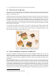
Fig. 3.2 is an example of a proper termination of a shielded cable. The inner jacket must be placed to
form a contact with the shielded Ethernet ports of the FM3500 ENDO to prevent any ESD issue.
Shielded RJ45 Ethernet connectors must also be used.
Once the cabling is done properly, the RJ45 connectors can be plugged into the relative Ethernet port
of the FM3500 ENDO and the bottom can be locked using the retaining screws on the sides (view
installation guide).
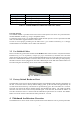
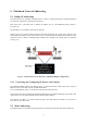
3.1.1 Status and Link LEDs
A panel on the back of the FM3500, shown in Fig. 3.1, provides seven (7) LEDs that can be used to
check the unit and the link quality status. From the left-hand side, the first 3 green LEDs indicate
the unit power, the Ethernet port #1 activity and the Ethernet port #2 activity, respectively. The
remaining 4 colored LEDs indicate the level of the link signal and can be used for antenna alignment
purposes. During the unit boot-up process, the 4 colored LEDs indicate the boot status and can be
used for problem detection. In fact, the LEDs light up in sequence from the leftmost one (red) to
rightmost one (bright green). If the LEDs lighting up sequence does not complete, then an error has
been detected during the booting process. Please refer to Table 3.1 for details.
Fig. 3.1 - From left to right status LEDs, link/boot LEDs