
User's Manual


3
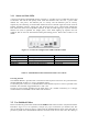
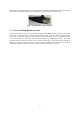
3.1.1 Status and Link LEDs
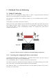
A panel on the back of the FM3200, shown in Figure 3.3, provides seven (7) LEDs that can be used
to check the unit and the link quality status. From the left-hand side, the first 3 green LEDs
indicate the unit power, the Ethernet port #1 activity and the Ethernet port #2 activity,
respectively. The remaining 4 colored LEDs indicate the level of the link signal and can be used for
antenna alignment purposes. During the unit boot-up process, the 4 colored LEDs indicate the
boot status and can be used for problem detection. In fact, the LEDs light up in sequence from the
leftmost one (red) to rightmost one (bright green). If the LEDs lighting up sequence does not
complete, then an error has been detected during the booting process. Please refer to Table 3.1 for
details.
Figure 3.3: From Left To Right Status LEDs, Link/Boot LEDs
LED$#$(Color)
!
Boot$Status
!
Link$ Quality!
1$(Red)
!
"##$%&'!(#)*!+,+$*-
!
.##)/0%&1!23+*&$
!
2$(Orange)
!
"##$%&'!4%)*0*++!+,+$*-
!
52%)!
3$(Green)
!
"##$%&'!)#6 $%&'!*&'%&*
!
7##8
!
4$(Green)
!
"##$%&'!6&%$!(#&9%'6)2$%#&
!
:*),!'##8
!
Table 3.1: FM3200 BASE Boot/Link Status LEDs Color Scheme
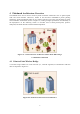
Powering the unit
The FM3200 BASE is provided with a 48V Passive PoE Injector and can be also powered with a
standard IEEE802.3af PoE (e.g. using a compatible switch).
To minimize power losses, it is recommended to install the PoE injector as close as possible to the
FM radio. The maximum suggested distance is 50ft / 15m.
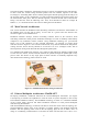
In order to secure proper grounding for the radio and to get a reliable connectivity, it is strongly
recommended to use shielded CAT5/6 cables and connectors.
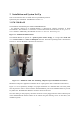
3.2 Use Shielded Cables
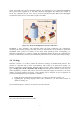
Please note that only professional outdoor-rated shielded cables must be used in conjunction with the
FM radios. Figure 3.13 is an explanatory example of a proper termination of a shielded cable. The
inner jacket must be placed to form a contact with the shielded Ethernet ports of the FM radio to
prevent any ESD issue. Shielded RJ45 Ethernet connectors must also be used. Once the cabling is