
Installation Instructions
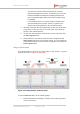
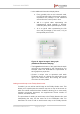
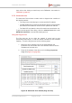
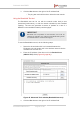
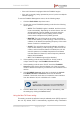
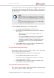
Table Of Contents
- Fluidmesh 4200 FIBER
- Table of Contents
- 1. HAZARDOUS CONDITION WARNINGS
- 2. Reporting mistakes and recommending improvements
- 3. Getting Started
- 4. Hardware installation
- 4.1. Fluidmesh Hardware Installation
- 4.2. Connecting the Fluidmesh Fluidmesh 4200 FIBER to a network and antennas
- 5. Using the Fluidmesh Partner Portal
- 6. Device configuration using the configurator interface
- 6.1. Software and hardware prerequisites
- 6.2. Accessing the Fluidmesh 4200 FIBER for device configuration
- 6.3. Switching between offline and online modes
- 6.4. General settings
- 6.5. Network control
- 6.6. Advanced settings
- 6.6.1. Advanced radio settings
- 6.6.2. SFP settings
- 6.6.3. Static routes
- 6.6.4. Whitelists and Blacklists
- 6.6.5. Multicast
- 6.6.6. SNMP configuration
- 6.6.7. Wireless access point configuration
- 6.6.8. RADIUS configuration
- 6.6.9. NTP Configuration
- 6.6.10. L2TP configuration
- 6.6.11. VLAN settings
- 6.6.12. Fluidity settings
- 6.6.13. Miscellaneous settings
- 6.7. Management settings
- 6.7.1. View Mode settings
- 6.7.2. Changing the Administrator username and password
- 6.7.3. Overwriting and upgrading the unit firmware
- 6.7.4. Plug-In management
- 6.7.5. The device status view
- 6.7.6. Saving and restoring the unit settings
- 6.7.7. Resetting the unit to factory defaults
- 6.7.8. Logging out
- 6.7.9. Viewing the end-user license agreement
- 7. Software Plug-Ins
- 8. Troubleshooting
- 9. Electrical power requirements
- 10. Heat radiation data
- 11. Federal Communications Commission (FCC) radio interference statement
- 12. Notices and copyright
- 13. Fluidmesh end-user license agreement
- 13.1. Preamble
- 13.2. Notice
- 13.3. Definitions
- 13.4. License grant
- 13.5. Uses and restrictions on use
- 13.6. Open-source software
- 13.7. Termination
- 13.8. Feedback
- 13.9. Consent to use of data
- 13.10. Warranty disclaimer
- 13.11. Limitation of liability
- 13.12. Exclusion of liability for emergency services
- 13.13. Export control
- 13.14. General
- 14. Contact us

• In the additional-information display below:
a. Every graded point on the horizontal scale,
from the left-hand side of the graph onwards,
represents the passage of one additional
second from the current point in time.
b. -45 is a typical value representing the
instantaneous signal strength in Decibel-
milliwatts (dBm) at the specified point in time.
c. 11 is a typical value representing the link
error rate percentage (in this case, 11%) at
the specified point in time.
Figure 43. Signal strength / time graph
(additional-information display)
• The Legend at the bottom of the graph lists the static
units that are represented by the colored lines. For
example, static unit 10.12.101.2 is represented on
each graph as a purple line.
• Choose a unique color to represent each static
Fluidmesh device by clicking the colored tile to the
right of the device name, and clicking the chosen
color from the color palette.
Adding an aerial map to the Fluidity Quadro view
If needed, you can add an aerial image to the Fluidity Quadro view. This
allows you to superimpose the network map over a map of the terrain on
which the mobile network has been installed, allowing you to more easily
visualize component placement, the approximate current location of
vehicles, and other factors.
The procedures for adding an aerial map to the Fluidity Quadro view, and
manipulating the map, are the same as for the FMQuadro view. For
instructions on how to add an aerial terrain map to the Fluidity Quadro
Fluidmesh 4200 FIBER
© Fluidmesh Networks LLC Page 94 of 180