
Installation Instructions
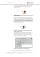
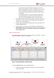
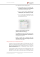
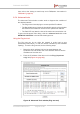
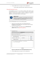
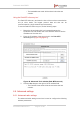
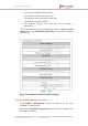
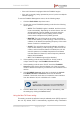
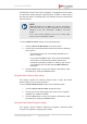
Table Of Contents
- Fluidmesh 4200 FIBER
- Table of Contents
- 1. HAZARDOUS CONDITION WARNINGS
- 2. Reporting mistakes and recommending improvements
- 3. Getting Started
- 4. Hardware installation
- 4.1. Fluidmesh Hardware Installation
- 4.2. Connecting the Fluidmesh Fluidmesh 4200 FIBER to a network and antennas
- 5. Using the Fluidmesh Partner Portal
- 6. Device configuration using the configurator interface
- 6.1. Software and hardware prerequisites
- 6.2. Accessing the Fluidmesh 4200 FIBER for device configuration
- 6.3. Switching between offline and online modes
- 6.4. General settings
- 6.5. Network control
- 6.6. Advanced settings
- 6.6.1. Advanced radio settings
- 6.6.2. SFP settings
- 6.6.3. Static routes
- 6.6.4. Whitelists and Blacklists
- 6.6.5. Multicast
- 6.6.6. SNMP configuration
- 6.6.7. Wireless access point configuration
- 6.6.8. RADIUS configuration
- 6.6.9. NTP Configuration
- 6.6.10. L2TP configuration
- 6.6.11. VLAN settings
- 6.6.12. Fluidity settings
- 6.6.13. Miscellaneous settings
- 6.7. Management settings
- 6.7.1. View Mode settings
- 6.7.2. Changing the Administrator username and password
- 6.7.3. Overwriting and upgrading the unit firmware
- 6.7.4. Plug-In management
- 6.7.5. The device status view
- 6.7.6. Saving and restoring the unit settings
- 6.7.7. Resetting the unit to factory defaults
- 6.7.8. Logging out
- 6.7.9. Viewing the end-user license agreement
- 7. Software Plug-Ins
- 8. Troubleshooting
- 9. Electrical power requirements
- 10. Heat radiation data
- 11. Federal Communications Commission (FCC) radio interference statement
- 12. Notices and copyright
- 13. Fluidmesh end-user license agreement
- 13.1. Preamble
- 13.2. Notice
- 13.3. Definitions
- 13.4. License grant
- 13.5. Uses and restrictions on use
- 13.6. Open-source software
- 13.7. Termination
- 13.8. Feedback
- 13.9. Consent to use of data
- 13.10. Warranty disclaimer
- 13.11. Limitation of liability
- 13.12. Exclusion of liability for emergency services
- 13.13. Export control
- 13.14. General
- 14. Contact us

• The assigned Unit ID and IP Address details for all
Fluidmesh units in the network will be shown.
NOTE
A user-assigned name can be given to each
unit in the network. For instructions on how to
re-name units, refer to “FMQuadro” (page 80).
2. Choose a unique color to represent each mobile Fluidmesh
device by clicking the colored tile to the right of the device’s mesh
ID number (5.a.b.c), and clicking the chosen color from the color
palette.
3. If needed, collapse the table by clicking the + button again.
The Vehicles table shows the following information:
• Each mobile transceiver unit that currently has a connection to one
or more static transceiver units is listed on the upper section of the
table.
• Each listing on the table represents a mobile unit or static unit that
can be seen on the Fluidity Quadro display.
• The following information is shown for each mobile unit listed in the
table:
1. Each mobile unit is represented by a chosen color on the
Fluidity Quadro display. For example, the first unit in the
table (5.0.4.136) has been assigned a medium blue color.
On the graph, this unit can be seen connected to Mesh
Point unit 5.0.41.58.
2. Collapse or expand the mobile unit listings as needed by
clicking the '-' or '+' button at the upper right-hand corner of
each listing.
3. The Mesh identity number (5.a.b.c) and local IP address of
each unit are shown in the color that has been assigned to
the unit.
4. Below each mobile unit listing is a graph showing signal
strength (in dBm) over time.
• Each colored line on the graph represents the
strength of the signal received by the mobile unit,
from a static unit that is part of the network. For
example, the signal strength between mobile unit
5.0.4.136 and static unit 10.12.101.5 is -43 dBm.
• To show additional information about the link
represented by a colored line, hover the mouse
cursor over the relevant colored line (Figure 43 (page
94)).
Fluidmesh 4200 FIBER
© Fluidmesh Networks LLC Page 93 of 180