
Installation Instructions
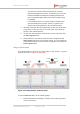
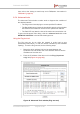
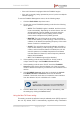
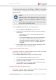
Table Of Contents
- Fluidmesh 4200 FIBER
- Table of Contents
- 1. HAZARDOUS CONDITION WARNINGS
- 2. Reporting mistakes and recommending improvements
- 3. Getting Started
- 4. Hardware installation
- 4.1. Fluidmesh Hardware Installation
- 4.2. Connecting the Fluidmesh Fluidmesh 4200 FIBER to a network and antennas
- 5. Using the Fluidmesh Partner Portal
- 6. Device configuration using the configurator interface
- 6.1. Software and hardware prerequisites
- 6.2. Accessing the Fluidmesh 4200 FIBER for device configuration
- 6.3. Switching between offline and online modes
- 6.4. General settings
- 6.5. Network control
- 6.6. Advanced settings
- 6.6.1. Advanced radio settings
- 6.6.2. SFP settings
- 6.6.3. Static routes
- 6.6.4. Whitelists and Blacklists
- 6.6.5. Multicast
- 6.6.6. SNMP configuration
- 6.6.7. Wireless access point configuration
- 6.6.8. RADIUS configuration
- 6.6.9. NTP Configuration
- 6.6.10. L2TP configuration
- 6.6.11. VLAN settings
- 6.6.12. Fluidity settings
- 6.6.13. Miscellaneous settings
- 6.7. Management settings
- 6.7.1. View Mode settings
- 6.7.2. Changing the Administrator username and password
- 6.7.3. Overwriting and upgrading the unit firmware
- 6.7.4. Plug-In management
- 6.7.5. The device status view
- 6.7.6. Saving and restoring the unit settings
- 6.7.7. Resetting the unit to factory defaults
- 6.7.8. Logging out
- 6.7.9. Viewing the end-user license agreement
- 7. Software Plug-Ins
- 8. Troubleshooting
- 9. Electrical power requirements
- 10. Heat radiation data
- 11. Federal Communications Commission (FCC) radio interference statement
- 12. Notices and copyright
- 13. Fluidmesh end-user license agreement
- 13.1. Preamble
- 13.2. Notice
- 13.3. Definitions
- 13.4. License grant
- 13.5. Uses and restrictions on use
- 13.6. Open-source software
- 13.7. Termination
- 13.8. Feedback
- 13.9. Consent to use of data
- 13.10. Warranty disclaimer
- 13.11. Limitation of liability
- 13.12. Exclusion of liability for emergency services
- 13.13. Export control
- 13.14. General
- 14. Contact us

• The device's maximum Ethernet capacity and current
Ethernet throughput are shown. This allows you to monitor
Ethernet utilization and determine whether the Ethernet
port is overutilized (particularly if the Fluid Throttle plug-in
is installed).
• If a Fluidmesh device is not performing as expected, the
dot representing the unit turns yellow. If a yellow dot is
clicked, the warning details for the unit will be shown.
4. All static Fluidmesh devices represented by dots can be placed in
any position on the map view. To move any dot, click-and-drag
the dot to the needed position.
5. To save the network layout currently seen on the map view, click
the Save Layout button.
6. If the positions of any device dots have been changed and the
Save Layout button has not yet been clicked, you can restore the
visual network layout to its last saved configuration by clicking the
Load Layout button.
Using the Vehicles table
The Vehicles table is found at the lower edge of the window. A typical
example is shown in (Figure 42 (page 92)).
Figure 42. Fluidity Quadro (Vehicles table)
To use the Vehicles table, do the following steps:
1. Expand the table by clicking the + button at the upper right-hand
corner of the table.
Fluidmesh 4200 FIBER
© Fluidmesh Networks LLC Page 92 of 180