
Installation Instructions
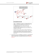
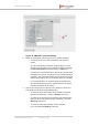
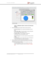
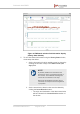
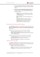
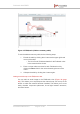
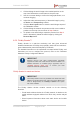
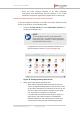
Table Of Contents
- Fluidmesh 4200 FIBER
- Table of Contents
- 1. HAZARDOUS CONDITION WARNINGS
- 2. Reporting mistakes and recommending improvements
- 3. Getting Started
- 4. Hardware installation
- 4.1. Fluidmesh Hardware Installation
- 4.2. Connecting the Fluidmesh Fluidmesh 4200 FIBER to a network and antennas
- 5. Using the Fluidmesh Partner Portal
- 6. Device configuration using the configurator interface
- 6.1. Software and hardware prerequisites
- 6.2. Accessing the Fluidmesh 4200 FIBER for device configuration
- 6.3. Switching between offline and online modes
- 6.4. General settings
- 6.5. Network control
- 6.6. Advanced settings
- 6.6.1. Advanced radio settings
- 6.6.2. SFP settings
- 6.6.3. Static routes
- 6.6.4. Whitelists and Blacklists
- 6.6.5. Multicast
- 6.6.6. SNMP configuration
- 6.6.7. Wireless access point configuration
- 6.6.8. RADIUS configuration
- 6.6.9. NTP Configuration
- 6.6.10. L2TP configuration
- 6.6.11. VLAN settings
- 6.6.12. Fluidity settings
- 6.6.13. Miscellaneous settings
- 6.7. Management settings
- 6.7.1. View Mode settings
- 6.7.2. Changing the Administrator username and password
- 6.7.3. Overwriting and upgrading the unit firmware
- 6.7.4. Plug-In management
- 6.7.5. The device status view
- 6.7.6. Saving and restoring the unit settings
- 6.7.7. Resetting the unit to factory defaults
- 6.7.8. Logging out
- 6.7.9. Viewing the end-user license agreement
- 7. Software Plug-Ins
- 8. Troubleshooting
- 9. Electrical power requirements
- 10. Heat radiation data
- 11. Federal Communications Commission (FCC) radio interference statement
- 12. Notices and copyright
- 13. Fluidmesh end-user license agreement
- 13.1. Preamble
- 13.2. Notice
- 13.3. Definitions
- 13.4. License grant
- 13.5. Uses and restrictions on use
- 13.6. Open-source software
- 13.7. Termination
- 13.8. Feedback
- 13.9. Consent to use of data
- 13.10. Warranty disclaimer
- 13.11. Limitation of liability
- 13.12. Exclusion of liability for emergency services
- 13.13. Export control
- 13.14. General
- 14. Contact us

3. Fine-tune the statistical displays by clicking-and-dragging
the Zoom period sliders to adjust the period that must be
viewed.
4. Check any or all of the information category check-boxes
in the View: section of the window. Depending on the
check-box selections, relevant statistical information will
be shown as follows:
• TX Rate: Current link transmission rate, in Mb/s.
• Throughput: Rate of successful message delivery
over the wireless link.
• Signal Strength: Current received signal level, in
dBm.
• Packet Error Rate: Percentage of packets
dropped due to excessive transmission errors.
• Link Error Rate: Percentage of packet re-
transmissions due to transmission errors.
Interpreting device warnings and wireless link warnings
If the Warnings check-box in the check-box panel at the top of the
window is checked (Figure 31 (page 81)), all visual warnings for all
devices and wireless links that are not currently performing as expected
will be shown.
Visual warnings that may be shown for radio units are as follows:
• Ethernet Capacity Overflow (Plug-in capacity exceeded)
• Hidden Terminal Detected (A hidden terminal has been detected
by the FluidMAX engine)
Visual warnings that may be shown for wireless links are as follows:
• Low Signal Strength (Link signal strength is less than 60%)
• High Error Rate (Packet error rate is more than 5%)
• High Link Congestion (Link utilization is more than 80%)
Using the address summary table
The Address Summary table is located at the lower left corner of the
window (Figure 35 (page 87)). This table shows the following information
for each radio transceiver unit in the network:
• Name: The user-assigned name of each unit.
• Unit ID: The unique 5.a.b.c Fluidmesh unit identification number.
• IP Address: The IP address of the unit within the network.
Fluidmesh 4200 FIBER
© Fluidmesh Networks LLC Page 86 of 180