
Installation Instructions
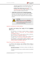
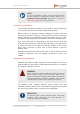
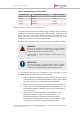
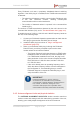
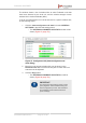
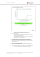
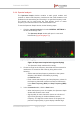
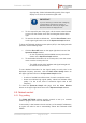
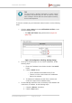
Table Of Contents
- Fluidmesh 4200 FIBER
- Table of Contents
- 1. HAZARDOUS CONDITION WARNINGS
- 2. Reporting mistakes and recommending improvements
- 3. Getting Started
- 4. Hardware installation
- 4.1. Fluidmesh Hardware Installation
- 4.2. Connecting the Fluidmesh Fluidmesh 4200 FIBER to a network and antennas
- 5. Using the Fluidmesh Partner Portal
- 6. Device configuration using the configurator interface
- 6.1. Software and hardware prerequisites
- 6.2. Accessing the Fluidmesh 4200 FIBER for device configuration
- 6.3. Switching between offline and online modes
- 6.4. General settings
- 6.5. Network control
- 6.6. Advanced settings
- 6.6.1. Advanced radio settings
- 6.6.2. SFP settings
- 6.6.3. Static routes
- 6.6.4. Whitelists and Blacklists
- 6.6.5. Multicast
- 6.6.6. SNMP configuration
- 6.6.7. Wireless access point configuration
- 6.6.8. RADIUS configuration
- 6.6.9. NTP Configuration
- 6.6.10. L2TP configuration
- 6.6.11. VLAN settings
- 6.6.12. Fluidity settings
- 6.6.13. Miscellaneous settings
- 6.7. Management settings
- 6.7.1. View Mode settings
- 6.7.2. Changing the Administrator username and password
- 6.7.3. Overwriting and upgrading the unit firmware
- 6.7.4. Plug-In management
- 6.7.5. The device status view
- 6.7.6. Saving and restoring the unit settings
- 6.7.7. Resetting the unit to factory defaults
- 6.7.8. Logging out
- 6.7.9. Viewing the end-user license agreement
- 7. Software Plug-Ins
- 8. Troubleshooting
- 9. Electrical power requirements
- 10. Heat radiation data
- 11. Federal Communications Commission (FCC) radio interference statement
- 12. Notices and copyright
- 13. Fluidmesh end-user license agreement
- 13.1. Preamble
- 13.2. Notice
- 13.3. Definitions
- 13.4. License grant
- 13.5. Uses and restrictions on use
- 13.6. Open-source software
- 13.7. Termination
- 13.8. Feedback
- 13.9. Consent to use of data
- 13.10. Warranty disclaimer
- 13.11. Limitation of liability
- 13.12. Exclusion of liability for emergency services
- 13.13. Export control
- 13.14. General
- 14. Contact us

signal quality. Yellow indicates falling quality. If the signal
display is red, there is excessive signal noise.
IMPORTANT
If you are scanning a network with overlapping
communication channels, the number of
detected Fluidmesh units may be larger than
the actual number of deployed units.
4. To view a specific part of the graph, roll the mouse wheel forward
to zoom into the window, then click-and-drag the window left or
right.
5. To reset the window to default size, click the Reset Zoom button
on the upper right-hand corner of the Spectrum Graph window.
To show all Fluidmesh wireless access points (APs) in the displayed radio
spectrum, do the following steps:
1. Click the Show AP button on the upper right-hand corner of the
Spectrum Graph window.
• An icon representing each available access point will be
shown on the Spectrum Graph window.
2. To see detailed information for an access point, hover the mouse
cursor over the access point icon.
• The SSID number, MAC address and signal strength will
be shown for the chosen AP.
To see detailed information for the signal quality at each point in the
displayed frequency spectrum, click the Show Chan Quality button on
the upper right-hand corner of the Spectrum Graph window.
• A series of vertical bars will be shown for each occupied channel.
• Green bars indicate high signal quality. Yellow bars indicate falling
quality. If a bar is red, there is excessive signal noise at that
frequency.
To close the Spectrum Graph web page, click the Close Window
button on the upper right-hand corner of the Spectrum Graph window.
6.5. Network control
6.5.1. Ping softdog
The PING SOFTDOG window contains controls to set up a constant
series of pings to one or more IP addresses.
If connectivity is lost between the unit and any of the saved IP addresses,
an option can also be set to automatically reboot the Fluidmesh 4200
FIBER.
Fluidmesh 4200 FIBER
© Fluidmesh Networks LLC Page 78 of 180