
Installation Instructions

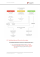
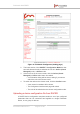
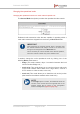
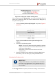
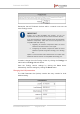
Table Of Contents
- Fluidmesh 4200 FIBER
- Table of Contents
- 1. HAZARDOUS CONDITION WARNINGS
- 2. Reporting mistakes and recommending improvements
- 3. Getting Started
- 4. Hardware installation
- 4.1. Fluidmesh Hardware Installation
- 4.2. Connecting the Fluidmesh Fluidmesh 4200 FIBER to a network and antennas
- 5. Using the Fluidmesh Partner Portal
- 6. Device configuration using the configurator interface
- 6.1. Software and hardware prerequisites
- 6.2. Accessing the Fluidmesh 4200 FIBER for device configuration
- 6.3. Switching between offline and online modes
- 6.4. General settings
- 6.5. Network control
- 6.6. Advanced settings
- 6.6.1. Advanced radio settings
- 6.6.2. SFP settings
- 6.6.3. Static routes
- 6.6.4. Whitelists and Blacklists
- 6.6.5. Multicast
- 6.6.6. SNMP configuration
- 6.6.7. Wireless access point configuration
- 6.6.8. RADIUS configuration
- 6.6.9. NTP Configuration
- 6.6.10. L2TP configuration
- 6.6.11. VLAN settings
- 6.6.12. Fluidity settings
- 6.6.13. Miscellaneous settings
- 6.7. Management settings
- 6.7.1. View Mode settings
- 6.7.2. Changing the Administrator username and password
- 6.7.3. Overwriting and upgrading the unit firmware
- 6.7.4. Plug-In management
- 6.7.5. The device status view
- 6.7.6. Saving and restoring the unit settings
- 6.7.7. Resetting the unit to factory defaults
- 6.7.8. Logging out
- 6.7.9. Viewing the end-user license agreement
- 7. Software Plug-Ins
- 8. Troubleshooting
- 9. Electrical power requirements
- 10. Heat radiation data
- 11. Federal Communications Commission (FCC) radio interference statement
- 12. Notices and copyright
- 13. Fluidmesh end-user license agreement
- 13.1. Preamble
- 13.2. Notice
- 13.3. Definitions
- 13.4. License grant
- 13.5. Uses and restrictions on use
- 13.6. Open-source software
- 13.7. Termination
- 13.8. Feedback
- 13.9. Consent to use of data
- 13.10. Warranty disclaimer
- 13.11. Limitation of liability
- 13.12. Exclusion of liability for emergency services
- 13.13. Export control
- 13.14. General
- 14. Contact us

Changing the operational mode
Changing the operational mode on a mesh network-capable unit
The General Mode box (below) contains the operational mode controls.
Fluidmesh radio transceiver units that are capable of operating within a
mesh radio network are shipped from the factory in Mesh End mode.
IMPORTANT
When designing the required network layout, remember that
the wireless network must always connect to the wired LAN
through a unit configured to be a Mesh End unit.
This is necessary for correct wireless mesh network operation,
even if the network consists only of two wireless units.
If needed, change the unit's operational mode by clicking one of the
following Mode: radio buttons:
• bridge (This mode creates a layer 2 connection between the local
unit and another Bridge unit.)
• mesh point (This mode allows you to use the unit as a relay point
in the mesh network and/or attach an IP edge device, such as a
CCTV camera or video encoder, to the unit.)
• mesh end (This mode allows you to install the unit as the junction
point between the wireless network and a wired LAN.)
NOTE
If the bridge option is chosen, the Fluidmesh device ID
number of the unit that forms the opposite side of the
wireless bridge will be shown in the Configurator
window heading block (Figure 24 (page 67)).
Fluidmesh 4200 FIBER
© Fluidmesh Networks LLC Page 66 of 180