
Installation Instructions
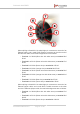
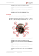
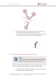
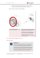
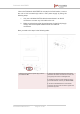
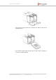
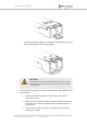
Table Of Contents
- Fluidmesh 4200 FIBER
- Table of Contents
- 1. HAZARDOUS CONDITION WARNINGS
- 2. Reporting mistakes and recommending improvements
- 3. Getting Started
- 4. Hardware installation
- 4.1. Fluidmesh Hardware Installation
- 4.2. Connecting the Fluidmesh Fluidmesh 4200 FIBER to a network and antennas
- 5. Using the Fluidmesh Partner Portal
- 6. Device configuration using the configurator interface
- 6.1. Software and hardware prerequisites
- 6.2. Accessing the Fluidmesh 4200 FIBER for device configuration
- 6.3. Switching between offline and online modes
- 6.4. General settings
- 6.5. Network control
- 6.6. Advanced settings
- 6.6.1. Advanced radio settings
- 6.6.2. SFP settings
- 6.6.3. Static routes
- 6.6.4. Whitelists and Blacklists
- 6.6.5. Multicast
- 6.6.6. SNMP configuration
- 6.6.7. Wireless access point configuration
- 6.6.8. RADIUS configuration
- 6.6.9. NTP Configuration
- 6.6.10. L2TP configuration
- 6.6.11. VLAN settings
- 6.6.12. Fluidity settings
- 6.6.13. Miscellaneous settings
- 6.7. Management settings
- 6.7.1. View Mode settings
- 6.7.2. Changing the Administrator username and password
- 6.7.3. Overwriting and upgrading the unit firmware
- 6.7.4. Plug-In management
- 6.7.5. The device status view
- 6.7.6. Saving and restoring the unit settings
- 6.7.7. Resetting the unit to factory defaults
- 6.7.8. Logging out
- 6.7.9. Viewing the end-user license agreement
- 7. Software Plug-Ins
- 8. Troubleshooting
- 9. Electrical power requirements
- 10. Heat radiation data
- 11. Federal Communications Commission (FCC) radio interference statement
- 12. Notices and copyright
- 13. Fluidmesh end-user license agreement
- 13.1. Preamble
- 13.2. Notice
- 13.3. Definitions
- 13.4. License grant
- 13.5. Uses and restrictions on use
- 13.6. Open-source software
- 13.7. Termination
- 13.8. Feedback
- 13.9. Consent to use of data
- 13.10. Warranty disclaimer
- 13.11. Limitation of liability
- 13.12. Exclusion of liability for emergency services
- 13.13. Export control
- 13.14. General
- 14. Contact us

• Terminal 4 of M12A (Orange wire) to terminal 2 of M12X.
• Terminal 5 of M12A (Green wire with white tracer) to terminal 3 of
M12X.
• Terminal 6 of M12A (Orange wire with white tracer) to terminal 1 of
M12X.
• Terminal 7 of M12A (Blue wire) to terminal 8 of M12X.
• Terminal 8 of M12A (Green wire) to terminal 4 of M12X.
M12 X-coded
M12 X-coded connectors are used on all Fluidmesh 4200-series and
4500-series units manufactured after September 2016.
When splicing a male M12 X-coded connector to one end of an Ethernet
cable, and a male RJ45 Ethernet connector to the other end of the
Ethernet cable, the terminal assignments are as follows:
•
Terminal 1 of M12X (Orange wire with white tracer) to terminal 1 of
RJ45.
• Terminal 2 of M12X (Orange wire) to terminal 2 of RJ45.
• Terminal 3 of M12X (Green wire with white tracer) to terminal 3 of
RJ45.
• Terminal 4 of M12X (Green wire) to terminal 6 of RJ45.
• Terminal 5 of M12X (Brown wire with white tracer) to terminal 7 of
RJ45.
• Terminal 6 of M12X (Brown wire) to terminal 8 of RJ45.
• Terminal 7 of M12X (Blue wire with white tracer) to terminal 5 of
RJ45.
Fluidmesh 4200 FIBER
© Fluidmesh Networks LLC Page 32 of 180