
Installation Instructions
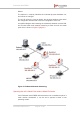
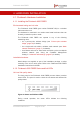
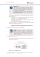
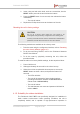
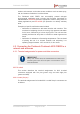
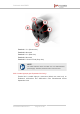
Table Of Contents
- Fluidmesh 4200 FIBER
- Table of Contents
- 1. HAZARDOUS CONDITION WARNINGS
- 2. Reporting mistakes and recommending improvements
- 3. Getting Started
- 4. Hardware installation
- 4.1. Fluidmesh Hardware Installation
- 4.2. Connecting the Fluidmesh Fluidmesh 4200 FIBER to a network and antennas
- 5. Using the Fluidmesh Partner Portal
- 6. Device configuration using the configurator interface
- 6.1. Software and hardware prerequisites
- 6.2. Accessing the Fluidmesh 4200 FIBER for device configuration
- 6.3. Switching between offline and online modes
- 6.4. General settings
- 6.5. Network control
- 6.6. Advanced settings
- 6.6.1. Advanced radio settings
- 6.6.2. SFP settings
- 6.6.3. Static routes
- 6.6.4. Whitelists and Blacklists
- 6.6.5. Multicast
- 6.6.6. SNMP configuration
- 6.6.7. Wireless access point configuration
- 6.6.8. RADIUS configuration
- 6.6.9. NTP Configuration
- 6.6.10. L2TP configuration
- 6.6.11. VLAN settings
- 6.6.12. Fluidity settings
- 6.6.13. Miscellaneous settings
- 6.7. Management settings
- 6.7.1. View Mode settings
- 6.7.2. Changing the Administrator username and password
- 6.7.3. Overwriting and upgrading the unit firmware
- 6.7.4. Plug-In management
- 6.7.5. The device status view
- 6.7.6. Saving and restoring the unit settings
- 6.7.7. Resetting the unit to factory defaults
- 6.7.8. Logging out
- 6.7.9. Viewing the end-user license agreement
- 7. Software Plug-Ins
- 8. Troubleshooting
- 9. Electrical power requirements
- 10. Heat radiation data
- 11. Federal Communications Commission (FCC) radio interference statement
- 12. Notices and copyright
- 13. Fluidmesh end-user license agreement
- 13.1. Preamble
- 13.2. Notice
- 13.3. Definitions
- 13.4. License grant
- 13.5. Uses and restrictions on use
- 13.6. Open-source software
- 13.7. Termination
- 13.8. Feedback
- 13.9. Consent to use of data
- 13.10. Warranty disclaimer
- 13.11. Limitation of liability
- 13.12. Exclusion of liability for emergency services
- 13.13. Export control
- 13.14. General
- 14. Contact us

• The DC IN connection is a 5-pin M12A port, exclusively designed to
accept passive 48 Vdc power.
• The LAN connection is an 8-pin M12X port, designed to connect
the unit to a local area network (LAN) switch and/or to an IEEE
802.3 48 Vdc power source.
• The SFP connection is a small form-factor pluggable (SFP) port,
exclusively designed to connect the unit to a duplex fiber-optic data
link.
IMPORTANT
The Fluidmesh 4200 FIBER is shipped from the factory with no
fiber-optic transceiver installed. For the unit to have fiber-optic
capability, the SFP port must be equipped with a separate
fiber-optic transceiver.
4.1.4. Rebooting the firmware and resetting the unit to factory
defaults
The Fluidmesh 4200 FIBER hardware can be rebooted and reset to
factory default condition using the procedures in this section.
IMPORTANT
The following procedure shows how to do a 'hard' (device
firmware) reboot. To do a 'soft' (device software) reboot, refer
to “Resetting the unit to factory defaults” (page 147).
To do a 'hard' (device firmware) reboot under emergency conditions (for
example, if the unit malfunctions), do the steps in the following sub-
section.
Device firmware reboot
1. Remove the Phillips-head screw labelled RESET at the bottom of
the unit (Figure 8 (page 27)).
Figure 8. Fluidmesh 4200 FIBER (Hardware RESET protective
screw)
Fluidmesh 4200 FIBER
© Fluidmesh Networks LLC Page 27 of 180