
Installation Instructions
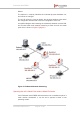
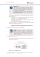
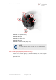
Table Of Contents
- Fluidmesh 4200 FIBER
- Table of Contents
- 1. HAZARDOUS CONDITION WARNINGS
- 2. Reporting mistakes and recommending improvements
- 3. Getting Started
- 4. Hardware installation
- 4.1. Fluidmesh Hardware Installation
- 4.2. Connecting the Fluidmesh Fluidmesh 4200 FIBER to a network and antennas
- 5. Using the Fluidmesh Partner Portal
- 6. Device configuration using the configurator interface
- 6.1. Software and hardware prerequisites
- 6.2. Accessing the Fluidmesh 4200 FIBER for device configuration
- 6.3. Switching between offline and online modes
- 6.4. General settings
- 6.5. Network control
- 6.6. Advanced settings
- 6.6.1. Advanced radio settings
- 6.6.2. SFP settings
- 6.6.3. Static routes
- 6.6.4. Whitelists and Blacklists
- 6.6.5. Multicast
- 6.6.6. SNMP configuration
- 6.6.7. Wireless access point configuration
- 6.6.8. RADIUS configuration
- 6.6.9. NTP Configuration
- 6.6.10. L2TP configuration
- 6.6.11. VLAN settings
- 6.6.12. Fluidity settings
- 6.6.13. Miscellaneous settings
- 6.7. Management settings
- 6.7.1. View Mode settings
- 6.7.2. Changing the Administrator username and password
- 6.7.3. Overwriting and upgrading the unit firmware
- 6.7.4. Plug-In management
- 6.7.5. The device status view
- 6.7.6. Saving and restoring the unit settings
- 6.7.7. Resetting the unit to factory defaults
- 6.7.8. Logging out
- 6.7.9. Viewing the end-user license agreement
- 7. Software Plug-Ins
- 8. Troubleshooting
- 9. Electrical power requirements
- 10. Heat radiation data
- 11. Federal Communications Commission (FCC) radio interference statement
- 12. Notices and copyright
- 13. Fluidmesh end-user license agreement
- 13.1. Preamble
- 13.2. Notice
- 13.3. Definitions
- 13.4. License grant
- 13.5. Uses and restrictions on use
- 13.6. Open-source software
- 13.7. Termination
- 13.8. Feedback
- 13.9. Consent to use of data
- 13.10. Warranty disclaimer
- 13.11. Limitation of liability
- 13.12. Exclusion of liability for emergency services
- 13.13. Export control
- 13.14. General
- 14. Contact us

IMPORTANT
The radio transceiver package does not include a DC IN power
source (devices capable of accepting DC IN power only), a
PoE injector, or a powered Ethernet switch. A suitable power
source must be ordered separately.
For technical data on which power sources are compatible with
the Fluidmesh 4200 FIBER, refer to “Electrical power
requirements” (page 165).
The Fluidmesh 4200 FIBER can be provided with power using the
following methods:
• A standard IEEE 802.3af Power-over-Ethernet (PoE) connection
(for example, from a compatible network switch).
• A compatible 48 Vdc passive PoE injector conforming to either
IEEE 802.3af or IEEE 802.3at.
• A 48 Vdc power source equipped with an M12A connector.
When providing the power source for the Fluidmesh 4200 FIBER,
remember the following important points:
• Install the power source as close to the unit as possible to minimize
voltage drop. The maximum suggested distance is 165ft (50m).
Connecting power to the Fluidmesh 4200 FIBER
NOTE
For detailed comparative information on which Fluidmesh
hardware devices are capable of accepting power
through IEEE 802.3at or IEEE 802.3af power sources, or
through a DC IN power source, refer to “Electrical power
requirements” (page 165).
DC IN, LAN and fiber-optic ports
The Fluidmesh 4200 FIBER radio transceiver unit has three connector
ports (Figure 7 (page 26)):
Figure 7. Device connector ports
Fluidmesh 4200 FIBER
© Fluidmesh Networks LLC Page 26 of 180