
Installation Instructions
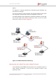
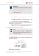
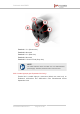
Table Of Contents
- Fluidmesh 4200 FIBER
- Table of Contents
- 1. HAZARDOUS CONDITION WARNINGS
- 2. Reporting mistakes and recommending improvements
- 3. Getting Started
- 4. Hardware installation
- 4.1. Fluidmesh Hardware Installation
- 4.2. Connecting the Fluidmesh Fluidmesh 4200 FIBER to a network and antennas
- 5. Using the Fluidmesh Partner Portal
- 6. Device configuration using the configurator interface
- 6.1. Software and hardware prerequisites
- 6.2. Accessing the Fluidmesh 4200 FIBER for device configuration
- 6.3. Switching between offline and online modes
- 6.4. General settings
- 6.5. Network control
- 6.6. Advanced settings
- 6.6.1. Advanced radio settings
- 6.6.2. SFP settings
- 6.6.3. Static routes
- 6.6.4. Whitelists and Blacklists
- 6.6.5. Multicast
- 6.6.6. SNMP configuration
- 6.6.7. Wireless access point configuration
- 6.6.8. RADIUS configuration
- 6.6.9. NTP Configuration
- 6.6.10. L2TP configuration
- 6.6.11. VLAN settings
- 6.6.12. Fluidity settings
- 6.6.13. Miscellaneous settings
- 6.7. Management settings
- 6.7.1. View Mode settings
- 6.7.2. Changing the Administrator username and password
- 6.7.3. Overwriting and upgrading the unit firmware
- 6.7.4. Plug-In management
- 6.7.5. The device status view
- 6.7.6. Saving and restoring the unit settings
- 6.7.7. Resetting the unit to factory defaults
- 6.7.8. Logging out
- 6.7.9. Viewing the end-user license agreement
- 7. Software Plug-Ins
- 8. Troubleshooting
- 9. Electrical power requirements
- 10. Heat radiation data
- 11. Federal Communications Commission (FCC) radio interference statement
- 12. Notices and copyright
- 13. Fluidmesh end-user license agreement
- 13.1. Preamble
- 13.2. Notice
- 13.3. Definitions
- 13.4. License grant
- 13.5. Uses and restrictions on use
- 13.6. Open-source software
- 13.7. Termination
- 13.8. Feedback
- 13.9. Consent to use of data
- 13.10. Warranty disclaimer
- 13.11. Limitation of liability
- 13.12. Exclusion of liability for emergency services
- 13.13. Export control
- 13.14. General
- 14. Contact us

• Power: The Fluidmesh 4200 FIBER is receiving power.
• LAN1: Network activity on Ethernet port 1.
• LAN2: Network activity on Ethernet port 2.
• SIGNAL STRENGTH (red): Signal strength very poor.
• SIGNAL STRENGTH (yellow): Signal strength inadequate.
• SIGNAL STRENGTH (green): Signal strength acceptable.
• SIGNAL STRENGTH (green): Signal strength excellent.
TIP
During normal operation, the readings from the four SIGNAL
STRENGTH LEDs can be used to do radio antenna alignment
(see “Antenna-alignment tools and physical statistics” (page
74) for more information).
Boot sequence
During the unit's boot sequence, the four SIGNAL STRENGTH LEDs light
up in sequence. During the boot sequence, the LEDs indicate the
following conditions:
1. Red: Core system boot in progress.
2. Yellow: Wireless system boot in progress.
3. First green: Routing engine boot in progress.
4. Second green: Unit configuration boot in progress.
If the boot sequence above stops at any LED, an error has been detected
during that stage of the boot sequence.
4.1.3. Supplying power to the Fluidmesh 4200 FIBER
CAUTION
When connecting the Fluidmesh 4200 FIBER to a power
supply, the instructions in this section must be strictly followed
at all times.
Failure to follow these instructions may result in irreparable
damage to the unit and/or other connected hardware, and will
also invalidate the product warranty.
Fluidmesh 4200 FIBER
© Fluidmesh Networks LLC Page 25 of 180