
Installation Instructions
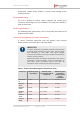
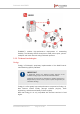
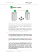
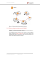
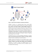
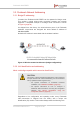
Table Of Contents
- Fluidmesh 4200 FIBER
- Table of Contents
- 1. HAZARDOUS CONDITION WARNINGS
- 2. Reporting mistakes and recommending improvements
- 3. Getting Started
- 4. Hardware installation
- 4.1. Fluidmesh Hardware Installation
- 4.2. Connecting the Fluidmesh Fluidmesh 4200 FIBER to a network and antennas
- 5. Using the Fluidmesh Partner Portal
- 6. Device configuration using the configurator interface
- 6.1. Software and hardware prerequisites
- 6.2. Accessing the Fluidmesh 4200 FIBER for device configuration
- 6.3. Switching between offline and online modes
- 6.4. General settings
- 6.5. Network control
- 6.6. Advanced settings
- 6.6.1. Advanced radio settings
- 6.6.2. SFP settings
- 6.6.3. Static routes
- 6.6.4. Whitelists and Blacklists
- 6.6.5. Multicast
- 6.6.6. SNMP configuration
- 6.6.7. Wireless access point configuration
- 6.6.8. RADIUS configuration
- 6.6.9. NTP Configuration
- 6.6.10. L2TP configuration
- 6.6.11. VLAN settings
- 6.6.12. Fluidity settings
- 6.6.13. Miscellaneous settings
- 6.7. Management settings
- 6.7.1. View Mode settings
- 6.7.2. Changing the Administrator username and password
- 6.7.3. Overwriting and upgrading the unit firmware
- 6.7.4. Plug-In management
- 6.7.5. The device status view
- 6.7.6. Saving and restoring the unit settings
- 6.7.7. Resetting the unit to factory defaults
- 6.7.8. Logging out
- 6.7.9. Viewing the end-user license agreement
- 7. Software Plug-Ins
- 8. Troubleshooting
- 9. Electrical power requirements
- 10. Heat radiation data
- 11. Federal Communications Commission (FCC) radio interference statement
- 12. Notices and copyright
- 13. Fluidmesh end-user license agreement
- 13.1. Preamble
- 13.2. Notice
- 13.3. Definitions
- 13.4. License grant
- 13.5. Uses and restrictions on use
- 13.6. Open-source software
- 13.7. Termination
- 13.8. Feedback
- 13.9. Consent to use of data
- 13.10. Warranty disclaimer
- 13.11. Limitation of liability
- 13.12. Exclusion of liability for emergency services
- 13.13. Export control
- 13.14. General
- 14. Contact us

3.3. Fluidmesh Network Addressing
3.3.1. Bridge IP addressing
If needed, the Fluidmesh 4200 FIBER can be operated in Bridge mode.
This creates a single point-to-point connection between two network
segments. A simplified example of a Bridge mode connection is shown
in Figure 4 (page 20).
As shipped from the factory, the wired ethernet ports of all Fluidmesh
hardware components are assigned the same default IP address of
192.168.0.10/24.
No default IP address is associated with the wireless interface.
Figure 4. Wireless network architecture (bridge configuration)
3.3.2. Unit identification and addressing
Mesh- and bridge-capable radio transceiver identification
CAUTION
This section contains theoretical explanations of the underlying
concepts behind mesh network addressing, and is intended for
use by qualified network engineers only.
• For specific instructions on Fluidmesh hardware
installation, see “Hardware installation” (page 24).
• For specific instructions on how to configure a
Fluidmesh radio transceiver unit using the configurator
interface, see “Device configuration using the
configurator interface” (page 50).
Regardless of its configuration and operating mode, every Fluidmesh
radio transceiver is shipped from the factory with a unique unit
identification (ID) number. This number always takes the following form:
Fluidmesh 4200 FIBER
© Fluidmesh Networks LLC Page 20 of 180