
Installation Instructions
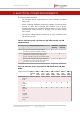
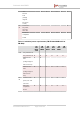

Table Of Contents
- Fluidmesh 4200 FIBER
- Table of Contents
- 1. HAZARDOUS CONDITION WARNINGS
- 2. Reporting mistakes and recommending improvements
- 3. Getting Started
- 4. Hardware installation
- 4.1. Fluidmesh Hardware Installation
- 4.2. Connecting the Fluidmesh Fluidmesh 4200 FIBER to a network and antennas
- 5. Using the Fluidmesh Partner Portal
- 6. Device configuration using the configurator interface
- 6.1. Software and hardware prerequisites
- 6.2. Accessing the Fluidmesh 4200 FIBER for device configuration
- 6.3. Switching between offline and online modes
- 6.4. General settings
- 6.5. Network control
- 6.6. Advanced settings
- 6.6.1. Advanced radio settings
- 6.6.2. SFP settings
- 6.6.3. Static routes
- 6.6.4. Whitelists and Blacklists
- 6.6.5. Multicast
- 6.6.6. SNMP configuration
- 6.6.7. Wireless access point configuration
- 6.6.8. RADIUS configuration
- 6.6.9. NTP Configuration
- 6.6.10. L2TP configuration
- 6.6.11. VLAN settings
- 6.6.12. Fluidity settings
- 6.6.13. Miscellaneous settings
- 6.7. Management settings
- 6.7.1. View Mode settings
- 6.7.2. Changing the Administrator username and password
- 6.7.3. Overwriting and upgrading the unit firmware
- 6.7.4. Plug-In management
- 6.7.5. The device status view
- 6.7.6. Saving and restoring the unit settings
- 6.7.7. Resetting the unit to factory defaults
- 6.7.8. Logging out
- 6.7.9. Viewing the end-user license agreement
- 7. Software Plug-Ins
- 8. Troubleshooting
- 9. Electrical power requirements
- 10. Heat radiation data
- 11. Federal Communications Commission (FCC) radio interference statement
- 12. Notices and copyright
- 13. Fluidmesh end-user license agreement
- 13.1. Preamble
- 13.2. Notice
- 13.3. Definitions
- 13.4. License grant
- 13.5. Uses and restrictions on use
- 13.6. Open-source software
- 13.7. Termination
- 13.8. Feedback
- 13.9. Consent to use of data
- 13.10. Warranty disclaimer
- 13.11. Limitation of liability
- 13.12. Exclusion of liability for emergency services
- 13.13. Export control
- 13.14. General
- 14. Contact us

9. ELECTRICAL POWER REQUIREMENTS
The following table describes:
• The electrical power requirements for each Fluidmesh hardware
device type.
• Which Fluidmesh hardware devices are capable of receiving power
through an IEEE 802.3 Ethernet port (whether from a power-
supplying device like a compatible network switch, or from a power-
over-Ethernet (PoE) injector), or through a DC IN power supply
port, or both.
• The specific voltage-variation tolerances of each Fluidmesh radio
transceiver unit type.
Table 9. Individual power requirements (FM 1000 Gateway and FM
10000 Gateway)
Required input power FM 1000
Gateway
FM 10000
Gateway
DC IN 12 Vdc (from mains AC power adapter
producing a minimum of 60W (12V/5A)).
X
AC IN Unit may be equipped with multiple 275W
redundant AC power supply units (input
power: 100 Vac to 240 Vac at 50 Hz to 60 Hz).
X
Unit may be equipped with single 250W non-
redundant AC power supply unit (input power:
100 Vac to 240 Vac at 50 Hz to 60 Hz).
X
Table 10. Individual power requirements (FM PONTE 50 to FM 4200
MOBI)
FM
PONTE
50
FM
1200
VOLO
FM
1300
OTTO
FM
3200
BASE
FM
3200
ENDO
FM
3200
+GPS
FM
3200
DEPOT
FM
4200
MOBI
PoE 24V
passive
PoE
X X
48V
passive
PoE
X X X X X
IEEE
802.3af
PoE
(voltage
range at
PD: 37V to
57V)
X X X X X X
Fluidmesh 4200 FIBER
© Fluidmesh Networks LLC Page 165 of 180