
Installation Instructions
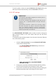
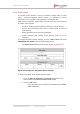
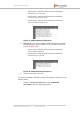
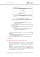
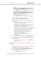
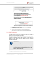
Table Of Contents
- Fluidmesh 4200 FIBER
- Table of Contents
- 1. HAZARDOUS CONDITION WARNINGS
- 2. Reporting mistakes and recommending improvements
- 3. Getting Started
- 4. Hardware installation
- 4.1. Fluidmesh Hardware Installation
- 4.2. Connecting the Fluidmesh Fluidmesh 4200 FIBER to a network and antennas
- 5. Using the Fluidmesh Partner Portal
- 6. Device configuration using the configurator interface
- 6.1. Software and hardware prerequisites
- 6.2. Accessing the Fluidmesh 4200 FIBER for device configuration
- 6.3. Switching between offline and online modes
- 6.4. General settings
- 6.5. Network control
- 6.6. Advanced settings
- 6.6.1. Advanced radio settings
- 6.6.2. SFP settings
- 6.6.3. Static routes
- 6.6.4. Whitelists and Blacklists
- 6.6.5. Multicast
- 6.6.6. SNMP configuration
- 6.6.7. Wireless access point configuration
- 6.6.8. RADIUS configuration
- 6.6.9. NTP Configuration
- 6.6.10. L2TP configuration
- 6.6.11. VLAN settings
- 6.6.12. Fluidity settings
- 6.6.13. Miscellaneous settings
- 6.7. Management settings
- 6.7.1. View Mode settings
- 6.7.2. Changing the Administrator username and password
- 6.7.3. Overwriting and upgrading the unit firmware
- 6.7.4. Plug-In management
- 6.7.5. The device status view
- 6.7.6. Saving and restoring the unit settings
- 6.7.7. Resetting the unit to factory defaults
- 6.7.8. Logging out
- 6.7.9. Viewing the end-user license agreement
- 7. Software Plug-Ins
- 8. Troubleshooting
- 9. Electrical power requirements
- 10. Heat radiation data
- 11. Federal Communications Commission (FCC) radio interference statement
- 12. Notices and copyright
- 13. Fluidmesh end-user license agreement
- 13.1. Preamble
- 13.2. Notice
- 13.3. Definitions
- 13.4. License grant
- 13.5. Uses and restrictions on use
- 13.6. Open-source software
- 13.7. Termination
- 13.8. Feedback
- 13.9. Consent to use of data
- 13.10. Warranty disclaimer
- 13.11. Limitation of liability
- 13.12. Exclusion of liability for emergency services
- 13.13. Export control
- 13.14. General
- 14. Contact us

IMPORTANT
Source and destination values are always unit
ID numbers. Do not enter a unit's IP address
as a source or destination value.
The unit ID number is printed on the
identification label of each unit. This number
always takes the following form: 5.a.b.c
• The smaller the routing priority value, the greater the
routing priority.
• Blacklist syntax is the same as shown above, except for
one additional rule: Blacklists do not include routing priority
numbers.
• Unit ID numbers and routing priority values are always
separated with commas (,) and never with spaces.
• To make sure that the packet flow is allowed or blocked in
both directions, the unit ID numbers for each link in a
Whitelist or Blacklist must be listed in forward order and in
reverse order.
• If a wireless link is not specified in a Whitelist, it will be
assigned the lowest routing priority, but will not be
completely excluded from routing.
3. Example 1: If you want to create a simple Whitelist that includes
the link between unit ID numbers 5.2.22.136 and 5.29.252.213
(Figure 50 (page 105)), and give the link routing priority 0 (the
highest possible priority):
• Cell A1 of the *.CSV file would contain the parameter
5.2.22.136,5.29.252.213,0
• Cell A2 of the *.CSV file would contain the parameter
5.29.252.213, 5.2.22.136,0
Figure 50. Sample Whitelist (Example 1)
4. Example 2: If you want to create a Whitelist that includes the
links between unit ID numbers 5.2.22.136 and 5.29.252.213 (with
routing priority 0), and between unit ID numbers 5.29.252.213
and 5.155.105.128 (with routing priority 1) (Figure 51 (page 106)):
• Cell A1 of the *.CSV file would contain the parameter
5.2.22.136,5.29.252.213,0
Fluidmesh 4200 FIBER
© Fluidmesh Networks LLC Page 105 of 180