® ® HARBIL NSC80 Compact Colorant Dispenser Operating and Instruction Manual Part # - 4700230 Rev.
CONFIDENTIAL PROPERTY OF FLUID MANAGEMENT® (C) COPYRIGHT 2001 FLUID MANAGEMENT AS AN UNPUBLISHED WORK ALL RIGHTS RESERVED This material cannot be copied or disclosed to others without the prior written permission of Fluid Management. FLUID MANAGEMENT A Unit of IDEX, Corp. 1023 Wheeling Road Wheeling, Illinois 60090-5776 Voice (847) 537-0880 US (800) 462-2466 Fax (847) 537-5530 www.fluidman.
TABLE OF CONTENTS Table Of Contents ASSEMBLY & INSTALLATION - - - - - - - - - - - - - - - - - - - - - - - 5 ASSEMBLY & INSTALLATION - - - - - - - - - - - - - - - - - - - - - - - 6 BASIC OPERATION - - - - - - - - - - - - - - - - - - - - - - - - - - - - - - 12 MAINTENANCE PROCEDURES - - - - - - - - - - - - - - - - - - - - - 13 PARTS: - - - - - - - - - - - - - - - - - - - - - - - - - - - - - - - - - - - - - - - - 14 NSC80 Operating & Instruction Manual 3
NOTES 4 Fluid na nt
ASSEMBLY & INSTALLATION ASSEMBLY & INSTALLATION INTRODUCTION The Harbil NSC80 is a compact manual colorant dispenser that was designed for exceptional reliability and ease of use. It is a nearly maintenance free device that should deliver many years of reliable service. Its features include: • Heavy-duty components and a durable finish for long wear. • Bottom agitation linked with rotation of the canisters. • Special adjustable shelving to accommodate all can sizes. SPECIFICATIONS Height 60" (152.
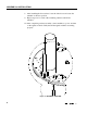
ASSEMBLY & INSTALLATION ASSEMBLY & INSTALLATION MOUNTING THE CANISTERS The Harbil NSC80 requires only the simple fastening of the individual canisters to the turntable. The canisters must be mounted in the proper order. Do not fill the canisters before that are mounted. It is critical that the crank be captured by the bushings that are part of the star wheel assembly.
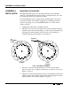
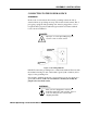
ASSEMBLY & INSTALLATION 5. Lower the canister into position, assuring that the agitation crank is captured by the nylon bushing and that the screw heads pass through the button holes, as shown in figure 3-A. Rotate canister clockwise locking it into place as shown in Figure 3-B. NOTE: The dispense port will fall through its hole, and the canister will sit flat on the turntable. 6. While holding canister in position, secure the canister to the turntable using a screwdriver.
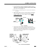
ASSEMBLY & INSTALLATION 8. After installing the first canister, lower the index lever and rotate the turntable to the next position. 9. Repeat steps 3-6 for each of the remaining canisters until all are installed. 10. After completing canister assembly, connect machine to power, and turn on the agitation switch. Verify that all the agitation blades are turning properly.
ASSEMBLY & INSTALLATION CONNECTING TO THE POWER SOURCE GROUNDING In the event of an electrical short circuit, grounding reduces the risk of electrical shock by providing an escape wire for the electric current. The 3prong plug, equipped with grounding wire, must be plugged into a 3-slot receptacle that is properly installed and grounded in accordance with all local codes and ordinances. DANGER: Improper use of the grounding plug can result in a risk of electric shock.
ASSEMBLY & INSTALLATION Connect the 115 volt models only to a 115 volt outlet rated at at least 15 ampere. Connect the 220 volt models only to a 220 volt outlet rated at at least 15 ampere. The equipment requires a single, grounded outlet. EXTENSION CORDS Extension cords for 220 VAC models are not recommended. If an extension cord is to be used, it should not be combined with others. Use only a 3-wire extension cord that has a 3-pole grounding plug.
ASSEMBLY & INSTALLATION FILLING CANISTERS After all of the canisters have been installed on the turntable, they can be filled. Each canister has a maximum capacity of 2-1/2 quarts. It is recommended that each canister be filled with two (2) quarts of colorant. The maximum capacity of the pump is two (2) ounces. The following steps represent the process by which the canisters should be filled: 1. Locate the first canister and determine which colorant is to be placed into that canister. 2.
BASIC OPERATION BASIC OPERATION This dispensing equipment is designed for ease of use. The following steps represent the method by which a formula is to be dispensed: 1. Determine the formula of the color selected by the customer. 2. Refer to the formula book and select the proper base paint. 3. Remove the lid on the base paint. 4. Pull out the appropriate shelf and place the can of base paint on the shelf. 5.
MAINTENANCE PROCEDURES MAINTENANCE PROCEDURES To ensure safe, dependable operation of the equipment, follow the maintenance schedule detailed below: DAILY Cleaning & Filling: • Agitate colorants every morning for five (5) to ten (10) minutes. • Clean nozzles & outside cabinet surfaces with soap and water. • Check canisters and fill as required. WEEKLY Cleaning & Nozzle Maintenance: • Dispense a full measure of any colorant that has not been used during the previous week.
PARTS: PARTS: EQUIPMENT MAINTENANCE LOG RECORD MODEL NUMBER HERE: _________________________ RECORD SERIAL NUMBER HERE: _________________________ SERVICE DATE 14 DESCRIPTION & PARTS REPLACED (STATE IF UNDER WARRANTY) SERVICED BY Fluid na nt
SPARE PARTS ORDER Fluid Management Parts Order Form Photocopy and use this form to Mail or fax orders to: Fluid Management A unit of IDEX 1023 Wheeling Road Wheeling, IL 60090 | | | | Phone: Fax: Sold To: Purchase Order Number: Ship Via: 1(800) 462-2466 1(847) 537-5530 Ship To: __________ ☐Collect ☐Prepaid ☐Tax Exempt (Fax copy of exemption PART QUANTITY NUMBER _____ ☐Taxable certificate.
PARTS: TURNTABLE (12 CANISTER SHOWN) CAP 25318 F0060T13XR (16 CANISTER) NUT 25033 07046 WASHER (12 CANISTER) 25249 BUSHING 24039 DRIVE PLATE CAM 25317 25219 (16 CANISTER) 25032 SPACERS (12 CANISTER) 25224 WHEEL 25222 CIRCLE SHEAR 25316 (16 CANISTER) 25030 (12 CANISTER) MOUNTING PLATE 25225 MOTOR 8100001 SWITCH 4000033 LEVER SPRING 4110906 SHELF 4110909 COUNTER TOP MODELS 16 Fluid na nt
PART NO 5/8”-11 1 PER CIRCLE SHEAR (12 CANISTER UNITS DRIVE PLATE (12 CANISTER UNITS TURNTABLE (12 CANISTER UNITS 25219 CAM ASSY 1 25222 WHEEL 5 25224 SPACER 10 25225 MOTOR MOUNTING PLATE 1 25249 5/8” FLAT WASHER 1 25318 TURNTABLE 1 4000033 POWER SWITCH 1 4110906 LEVER SPRING 1 4110909 SHELF 1 8100001 DRIVE MOTOR 1 CAP 1 F0030T13XR NSC80 Operating & Instruction Manual 17
PARTS: CAP TURNTABLE (12 CANISTER SHOWN) F0060T13XR 25318 (16 CANISTER) NUT 25033 07046 WASHER (12 CANISTER) 25249 BUSHING 24039 CAM 25219 WHEEL 25222 CIRCLE SHEAR 25316 (16 CANISTER) 25030 (12 CANISTER) DRIVE PLATE 25317 (16 CANISTER) 25032 (12 CANISTER) SPACER 25224 MOUNTING PLATE 25225 MOTOR 8100001 SWITCH 4000033 LEVER SPRING 4110906 KNOB 4000008 FLOOR MODELS 18 Fluid na nt
PART NO 5/8”-11 1 PER CIRCLE SHEAR (12 CANISTER UNITS DRIVE PLATE (12 CANISTER UNITS TURNTABLE (12 CANISTER UNITS 25219 CAM 1 25222 WHEEL 5 25224 SPACER 10 25225 MOTOR MOUNTING PLATE 1 25249 5/8” FLAT WASHER 1 25316 TURNTABLE (16 CANISTER UNITS ONLY) 1 25318 TURNTABLE (12 CANISTER UNITS ONLY) 1 4000008 BLACK 1 4000033 POWER SWITCH 1 4110906 LEVER SPRING 1 8100001 DRIVE MOTOR 1 CAP 1 F0060T13XR NSC80 Operating & Instruction Manual 19
PARTS: PIN 8101106 CRANK SHAFT 24382 CANISTER 4218000 AGITATION BLADE 23242 20 Fluid na nt
PART NO AGITATION 1 PER CRANK 1 PER TUBE (NOT 1 PER CANISTER (80 1 PER 4220209 PUMP TUBE AND PISTON (NOT SHOWN) 1 PER CANISTER 4228206 PUMP CAP INDICATOR (NOT SHOWN) 1 PER CANISTER 4220220 PUMP TUBE AND PISTON (NOT SHOWN) 1 PER CANISTER (METRIC UNITS ONLY) 4231000 VITON VALVE ASSY (NOT SHOWN) 1 PER CANISTER (VITON OR THIOKOL. NEEDED ONLY, NOT BOTH.) 4231070 THIOKOL VALVE ASSY (NOT SHOWN) 1 PER CANISTER (VITON OR THIOKOL. NEEDED ONLY, NOT BOTH.
PARTS: COVER 23245 (STANDARD) 24585 (FOR SOLVENTS) DRIVE PLATE 25032 CANISTER ASSEMBLY 25390 (1-OZ. PUMP W / VITON SEAL 4308001 (10-OZ. W / THIOKOL SEAL) TURNTABLE 25033 BOLT 02494 DRIVE PLATE 25317 12 CANISTER SYSTEM CANISTER ASSEMBLY 25390 (1-OZ. PUMP W / VITON SEAL 4308001 (10-OZ.
PART NO MOUNTING BOLT, 14 X 20 X 2 PER CANISTER COVER 1 PER CANISTER COVER (FOR 1 PER 25032 DRIVE PLATE (12 CANISTER UNITS) 1 25033 TURNTABLE (12 CANISTER UNITS) 1 25316 TURNTABLE (16 CANISTER UNITS) 1 25317 DRIVE PLATE (16 CANISTER UNITS) 1 25390 CANISTER ASSEMBLY (INCLUDES PUMP & VITON VALVE) 1 PER STATION (1-OZ. PUMP ONLY) 4000108 CANISTER ASSEMBLY (INCLUDES PUMP & THIOKOL VALVE ) 1 PER STATION (1-OZ.
Part No. 4700230 Rev. F 10/01/12 Fluid Management 1023 Wheeling Road Wheeling, Illinois 60090-5773 Telephone: (847) 537-0880 1-800-462-2466 Fax (847) 537-5530 www.fluidman.com Part No. 4700230 Rev.