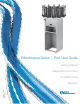
Blendorama Series | End User Guide Getting Started Maintenance and Care Troubleshooting Part No: 36321 Rev. 08.
Your customers have a vision, you want to make it happen, and Fluid Management can give you the answer. Fluid Management is a global leader in dispensing and mixing equipment used in the paint industry, as well as, specialized equipment for the food and beverage, chemical, health and beauty, and home improvement industries. Located in the suburbs of Chicago, Illinois, Fluid Management is a United States owned and operated company with historical roots to the paint industry dating back to 1927.
©2012 Fluid Management as published work all rights reserved. Under the copyright laws, this material may not be copied, in whole or in part, without the written consent of Fluid Management. Your rights to the software are governed by the accompanying software license agreement.
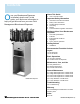
Contents O nce your Blendorama Dispenser is installed, what’s next? In this guide, you’ll find more information to help you get the most from your new Fluid Management Blendorama Dispenser.
About this Guide Safety Precautions How to Use this Guide • Read this guide and all warning labels before using the machine. This guide is organized into ten sections. Each section provides detailed information on Blendorama Series Dispenser topics and provides a basic reference that can be used to help you with specific issues. • Keep this guide in a safe place. • Read and adhere to all Warning and Caution labels on the machine. • Prepare, level, and clear the area where the machine will be installed.
Important Safety Information Information and Instruction Labels You should become familiar with the information labels affixed to the machine, as well as the warnings, cautions, and notes which appear throughout this guide. Read all the warning labels on the exterior and interior of the dispenser. If the labels become damaged or unreadable, you may purchase replacements from Fluid Management Customer Service.
Important Safety Information • Warnings This machine draws 3 amps at 120 ± 10% VAC. This machine draws 1.5 amps at 220/230 ±10% VAC. DO NOT modify the provided plug. Improper use of grounding plug can result in risk of electric shock. Hazardous moving parts. Keep fingers and other body parts away. • Grounding This product must be grounded. In the event of an electrical short circuit, grounding reduces the risk of electrical shock by providing an escape for the electric current.
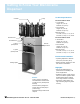
Getting to Know Your Blendorama Dispenser Canister Pump Technical Specifications Blendorama Model 25 PD 11-12 Canisters Height: 54” (137 cm) Diameter: 30” (76 cm) 14-16 Canisters Height: 54” (137 cm) Diameter: 32” (81 cm) Maximum power: 110 volts, 3.0 Amps +/- 10%, 60 Hz 220 volts, 1.
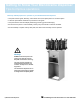
Getting to Know Your Blendorama Dispenser Tips to improve operations These tips will help improve the operation of your Blendorama Series Dispenser: • Keep this end-user guide, Allen key, valve sleeve wrench, and spare parts in a convenient place. • Follow the preventative maintenance procedures in this guide. • Keep the machine clean and display advertising promoting good housekeeping. • DO NOT use the piston or valve assembly of each pump as a handle to rotate the turntable.
Getting Started Installation Unpacking and Set up Follow the steps on the next three pages to set up your Blendorama Dispenser. • Warnings Important: Before you plug the Blendorama Series Dispenser into a power outlet, carefully read all of the following installation instructions and the safety information. It is recommended that at least one other person assist in taking the machine off the pallet.
Getting Started Installation (continued) For Exterior Perimeter Canisters 4 Select a canister assembly 5 Place the canister a. Fit the canister screws into the outer ring of the keyhold slots on the turntable. b. Push firmly into position (see page 13-15 for proper layouts). 6 Fix the canister into position a. Locate the 2 guide holes directly below each canister and fasten the Phillips-head screws located in the canister. b. Make sure the canister is firmly secured.
Getting Started Installation (continued) For Interior Canisters 4 Place the canister a. Firmly push the canister and connecting tube into the remote bracket and pump assembly. 5 Attach assembly to the turntable a. Fit Phillips-head screws located in the canister into the inner ring location keyholes. b. Fit the remote bracket into the 4 slots simultaneously and push firmly into position. Note: If the bracket face is not firm against the turntable edge, then the extension tube is not correctly fitted.
Getting Started Installation (continued) • It is important that the canisters are assembled and installed correctly to ensure stability of the canisters on the turntable and correct functioning of the stirring mechanism. 8 Lock the turntable in place a. Rotate the turntable until it engages into a locked position. b. Use the detent (or knob) lever to disengage and rotate the turntable. c. Leave the turntable in locked position.
Recommended Turntable Canister Layout Model 25 PD 11-canister format 12-canister format 14-canister format 16-canister format Fluid Management Customer Service 1.800.462.
Recommended Turntable Canister Layout Model 53 PD 9-canister with 4-dual canisters format 10-canister with 2-dual canisters format 12-canister format 12-canister with 3-dual canisters format 14 | Blendorama Dispenser Fluid Management Customer Service 1.800.462.
Recommended Turntable Canister Layout Model 53 PD (continued) 14-canister format 16-canister format 16-canister with 4-dual canisters format Fluid Management Customer Service 1.800.462.
Basic Operation First time operation 1 Prepare the dispenser a. Make sure the machine’s agitation is switched off at the wall socket. b. Stir each can of colorant thoroughly with a flat bottomed paddle or palette knife. c. Make sure that the machine is adequately supported and clear of obstructions. d. Remove the lids from all canisters. 16 | Blendorama Dispenser Fluid Management Customer Service 1.800.462.
Basic Operation First time operation (continued) e. Pour the contents of each colorant can into the correct canister. Discard the colorant can and replace the canister lid. 2 Purge the pumps a. Set the gauge of each pump to its halfway point by operating the spring loaded button then lifting the gauge by its handle. b. Without operating the valve lever lift the pump handle to its maximum travel (this draws the colorant into the canister). c.
Basic Operation First time operation (continued) 3 Purge the valve a. Lift the pump handle to its maximum travel. b. Place a container under the dispensing nozzle. c. Hold the valve lever open by pulling the spring loaded nozzle lever forward its full travel. d. Push the pump handle down fully to dispense colorant into the container. 18 | Blendorama Dispenser Fluid Management Customer Service 1.800.462.
Basic Operation First time operation (continued) e. Release the nozzle lever. f. Repeat this process until the colorant emerges as a steady stream. 4 Check the effectiveness of the purge a. Open the nozzle lever without operating the pump. A small drop of colorant will appear at the nozzle. b. Release the valve lever slowly and the drop will withdraw into the nozzle. Repeat this process 10 times.
Basic Operation General use of the dispenser 1 Select the color, base and can size a. Identify the color you wish to supply either by name or number b. Look up the tint formula and note the tint base required c. Identify the quantity required (can size) 2 Position the can a. Place the can on the appropriate can shelf. b. Adjust the height of the upper can shelf, if necessary. 3 Bring canister to the correct position a. Depress and hold the detent lever (or knob) to release the turntable. b.
Basic Operation General use of the dispenser (continued) 4 Set the gauges a. According to the setting required, operate the spring loaded button to release the gauge. The red knob is for the red gauge and the black knob is for the black gauge. b. With the appropriate button operated, lift the gauge to the reading required. c. The correct gauge setting is shown when the figure selected is fully exposed above the red handle and the gauge release button clicks firmly into place. 5 Charge the pump a.
Basic Operation General use of the dispenser (continued) 6 Discharge the pump a. While still holding the pump handle in the raised position, pull the spring-loaded valve lever (at the base of the pump) forward its full travel b. Holding the valve lever fully forward, press the red handle down with a smooth and steady stroke until the red handle is fully depressed. c. Ensure that both the red and black handles are fully depressed against the end cap.
Maintenance, Care, and Use Daily maintenance a. Clean the machine, refill canisters and check for blockages. b. Wipe down stand, canisters and pumps with a moistened cloth. c. Check nozzle outlets for dried colorants. d. If dried colorant is found to be blocking the nozzle, open the valve to remove and replace the nozzle. Ensure the O-ring is retained. Clean the nozzle using warm soapy water. e. Refit the nozzle and dispense a small amount of colorant. Fluid Management Customer Service 1.800.462.
Maintenance, Care, and Use Weekly maintenance a. Examine the machine for loose canisters and cylinder caps. Tighten if necessary. b. Examine gauges for damaged graduated scales or worn holes. Replace if necessary. c. Raise the pump handle to its maximum extension and examine the pump shafts for signs of colorant. This indicates that the piston seal will need replacement. 24 | Blendorama Dispenser Fluid Management Customer Service 1.800.462.
Maintenance, Care, and Use Periodic maintenance (every 3-6 months) a. Inspect the function of the valve and the canister for leaks. b. Make sure the machine is disconnected from the power source. c. Remove canister from turntable and drain colorant into a clean container. d. Remove stirrer paddle from canister and wash the canister, lid, and stirrer paddle. e. If required, tighten or replace the valve insert sleeve (with the wrench supplied). Take care not to over tighten or sleeve with crack.
Maintenance, Care, and Use Periodic maintenance (continued) f. Replace O-ring seal. g. Reassemble and refit canister to turntable. h. Return colorant to dispenser and prepare the pump for operation. • Caution Moving parts can cause injury. Always turn off power before accessing moving parts. 26 | Blendorama Dispenser Fluid Management Customer Service 1.800.462.
General Maintenance Gauge label replacement - Model 25 PD Before replacing the labels, calibrate the plungers as per the calibration instructions. Also make sure that the replacement label is the correct one - check the part numbers. a. Remove both black and red gauges. b. Peel the labels off both the red and black gauges. Remove all traces of adhesive (use a solvent if necessary). Wipe dry. c. Replace both gauges and set to the zero (fully down) position.
General Maintenance Gauge label replacement - Model 25 PD (continued) f. Carefully place the “0” line (the line below the numeral) of the label on the marked line of the gauge. g. Once in position, press the label firmly onto the gauge, ensuring it adheres to the gauge along its full length with no creases or bubbles (use a clean cloth to apply if necessary). h. Using a sharp knife or blade cut any excess label off the end of the gauge that may overlap the black plastic handle. i.
General Maintenance Gauge label replacement - Model 53 PD Before replacing the labels, calibrate the plungers as per the calibration instructions. Also make sure that the replacement label is the correct one - check the part numbers. a. Remove both black and red gauges. b. Peel the labels off both the red and black gauges. Remove all traces of adhesive (use a solvent if necessary). Wipe dry. c. Replace both gauges and set to the fully down position.
General Maintenance Gauge label replacement - Model 53 PD (continued) e. Peel the adhesive backing off the black label. f. Carefully place the first line of the label (the line below the first numeral) on the marked line of the gauge. g. Once in position, press the label firmly onto the gauge, ensuring it adheres to the gauge along its full length with no creases or bubbles (use a clean cloth to apply if necessary). h.
General Maintenance Gauge label replacement - Model 53 PD (continued) j. Align the end of the label up against the bottom edge of the gauge knob (the label is cut to size before leaving the factory). k. Once in position, press the label firmly onto the gauge, ensuring it adheres to the gauge along its full length with no creases or bubbles (use a clean cloth to apply if necessary). l. Refit the red gauge to the plunger. Fluid Management Customer Service 1.800.462.
General Maintenance Piston seals replacement - Model 25 PD 1 Replacement of the inner piston a. Loosen both grubscrews in the cylinder of the end cap (use Allen key) and remove the plunger assembly from the cylinder. Remove the gauges from the plunger assembly, then withdraw the inner plunger assembly from the hollow outer plunger shaft. Clean all colorant from both plunger assemblies. b. Using two pairs of pliers, grip the inner end of the piston with one and the piston shaft with the other.
General Maintenance Piston seals replacement - Model 25 PD (continued) c. Holding the end cap in one hand, pull the outer pump handle until the piston is fully withdrawn inside the end cap. 3 Returning plungers into cylinders a. After lightly oiling the top inside edge of the cylinder, position the plunger assembly on the cylinder with one hand. With the palm of the other hand, firmly push the plunger down fully. b. Tighten end cap assembly onto cylinder assembly using Allen key. c.
General Maintenance Piston seal replacement - Model 53 PD 1 Replacement of the inner piston a. Undo the knurled nut holding the cylinder end cap and remove the plunger assembly from the cylinder. Remove both gauges from the plunger assembly, withdraw the inner plunger assembly from the hollow outer plunger shaft and clean all colorant from both plunger assemblies. b. Using two pairs of pliers, grip the inner end of the piston with one and the piston shaft with the other.
General Maintenance Pump calibration - Model 25 PD 1 Outer pump calibration Recalibration of the pump is necessary if either of the original gauges have been replaced by another (for any reason). It is not required if only a gauge scale detail (Label) has been replaced. When recalibrating the pump, please leave the pump/canister fixed in place on the machine. Tools required: 1 x Allen (hex) key 3/32” A/F a.
General Maintenance Pump calibration - Model 25 PD (continued) 2 Inner pump calibration a. To calibrate the inner (red) plunger, refit the inner (red) gauge and plunger removed in step (1). Set the inner (red) gauge to zero. b. Using the Allen key, undo the calibration grubscrew in the red pump handle until free movement can be felt in the handle. Carefully wind the grubscrew back down until no free movement can be felt between the red pump handle and the red gauge knob. Be careful not to over-adjust.
General Maintenance Pump calibration - Model 53 PD 1 Outer pump calibration Recalibration of the pump is necessary if either of the original gauges have been replaced by another (for any reason). It is not required if only a gauge scale detail (Label) has been replaced. When recalibrating the pump, please leave the pump/canister fixed in place on the machine. Tools required: 1 x Allen (hex) key 3/32” A/F a.
Troubleshooting Most of the problems listed in this section can be prevented by daily cleaning and by purging the nozzle. See the Maintenance, Care and Use section in this manual for instructions. Use the chart below to locate the problem and perform the recommended actions in the last column. Contact Fluid Management Customer Service if you are unable to find a resolution.
Index B basic operation 16-22 C canister layout 13-15 charge the pump 21 cleaning 38 communications regulation information 6 container placement 18 D daily maintenance 21 discharge the pump 23 E environmental conditions 7 F features 7 feet 10 flammable materials 4, 5, 9 FMDirect 1, 4 G general safety information 5 grounding 6 I installation 9-10 L labels 4, 5, 27, 29 label replacement, model 25 PD 27 label replacement, model 53 PD 29 M maintenance 23-25, 38 P position canister 20 periodic maintenance 25 pr
Blendorama Series Dispenser Fluid Management, Inc. 1023 Wheeling Road • Wheeling IL 60090 p: 800.462.2466 f: 847.537.3221 www.fluidman.