Installation, Operation and Maintenance ® TM Nuclear Qualified FLT 93 Series FlexSwitch Flow, Level, Temperature Switch/Monitor Models: FLT93F, FLT93L, FLT93S ] [ Doc 06EN003409
FLT® Series FlexSwitchTM Notice of Proprietary Rights This document contains confidential technical data, including trade secrets and proprietary information which is the property of Fluid Components International LLC (FCI). Disclosure of this data to you is expressly conditioned upon your assent that its use is limited to use within your company only (and does not include manufacture or processing uses). Any other use is strictly prohibited without the prior written consent of FCI.
FLT® Series FlexSwitchTM 06EN003409 Rev. - Table of Contents 1 GENERAL ...................................................................................................................................................................................................7 Description...................................................................................................................................................................................................................
06EN003409 Rev. - FLT® Series FlexSwitchTM Level Applications .................................................................................................................................................................................................... 28 Temperature Applications ........................................................................................................................................................................................
FLT® Series FlexSwitchTM 06EN003409 Rev. - APPENDIX A DRAWINGS .........................................................................................................................................................................45 APPENDIX B GLOSSARY ..........................................................................................................................................................................47 APPENDIX C TEMPERATURE COMPENSATION ..............................................
FLT® Series FlexSwitchTM INTENTIONALLY LEFT BLANK 6 Fluid Components International LLC
FLT® Series FlexSwitchTM 1 GENERAL GENERAL Description The FLT Series models are multipurpose measurement instruments. The FLT Series models that are included in this manual are FLT93-S, FLT93-F, FLT93-HT and FLT93-L. Each model is a single instrument that is capable of detecting fluid flow and temperature. It is also able to detect liquid level or fluid media interfaces. The instrument has two field adjustable alarm set points, two buffered voltage outputs, as well as a built-in calibration circuit.
TECHNICAL SPECIFICATIONS FLT® Series FlexSwitchTM Technical Specification Application Flow rate and /or level /interface and temperature sensing in liquid, gas and slurry applications. Sensing Elements Process Connection Models S and F 3/4 inch male NPT standard; optional 1 inch BSP, 1 inch male NPT, 3/4 inch Male NPT (FLT93-F only); flanges, or spool pieces. Model L 1” male NPT or 3/4” female NPT, both ends with orifice; flanges optional.
FLT® Series FlexSwitchTM Factory Calibrated Switch Point Accuracy Any flow rate within the instrument flow range may be selected as a setpoint alarm. A factory-calibrated setpoint adjustment may be optimally preset with accuracy of ±2% of setpoint velocity over an operating temperature range of ±50°F [±28°C].
FLT® Series FlexSwitchTM INTENTIONALLY LEFT BLANK 10 Fluid Components International LLC
FLT® Series FlexSwitchTM 2 INSTALLATION INSTALLATION Receiving/Inspection • • • Unpack carefully. Verify that all items in the packing list are received and are correct. Inspect all instruments for damage or contaminants prior to installation. If the above three items are satisfactory, proceed with the installation. If not, then stop and contact a customer service representative. Packing/Shipping/Returns These issues are addressed in Appendix D - Customer Service.
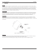
INSTALLATION FLT® Series FlexSwitchTM Verify Sensing Element Flow Direction and Placement Orientation (Level Application) If the sensing element is side-mounted on the process vessel, then the surface marked with direction arrows should be vertically oriented. If the sensing element is top- or bottom-mounted on the process vessel, the orientation of the surface marked with direction arrows does not matter.
FLT® Series FlexSwitchTM INSTALLATION Packing Gland Assembly 1. Threaded or flanged packing gland mounts are available. The valve assembly with appropriate connections are customer supplied. Follow the male NPT mounting procedure above to attach the pipe thread portion or flange mounting portion as applicable. 2. Tighten the packing nut until the internal packing is tight enough so that the friction fit on the shaft is adequate to prevent leakage but not prevent the shaft from sliding.
INSTALLATION FLT® Series FlexSwitchTM Install and Wire the Enclosure(s) Caution: In applications where the sensing element is located in an explosive environment, isolate the conduit before it leaves the environment. A potting Y may be used to provide the isolation. Pulling wires can cause damage to the control circuit. Therefore, remove the control circuit from the enclosure and use extreme care when pulling wires into the enclosure.
FLT® Series FlexSwitchTM INSTALLATION Wiring the Local Enclosure This procedure is for instruments with the control circuit located in the sensing element enclosure. 1. Remove the control circuit from its socket. Do not remove the control circuit socket. Removal of the control circuit socket may cause damage to the instrument. 2. Install conduit between the local enclosure and the power source and monitoring circuit.
INSTALLATION FLT® Series FlexSwitchTM Figure 2-6 Remote Wiring Diagram relay board is in the same enclosure as the control circuit. Both boards are mounted on the same panel and have been wired together at the factory. This configuration can be ordered without an enclosure which can be supplied by the customer. The alarm connections are made at the auxiliary relay board where each alarm is driving a DPDT relay. Caution: Do not connect any loads to the control circuit socket.
FLT® Series FlexSwitchTM INSTALLATION Figure 2-7 Auxilliary Relay Board Wiring Diagram Wiring Output Signal Terminals Two output signals are provided on the control circuit at P1. The signal voltage at positions 1 and 2 represents the process change. The signal voltage at positions 3 and 4 is proportional to the temperature at the sensing element. See Figures 2-5 through 2-7. See also Chapter 3 for the physical layout of the control circuit. Caution: Do not ground terminal 2 of P1.
INSTALLATION FLT® Series FlexSwitchTM INTENTIONALLY LEFT BLANK 18 Fluid Components International LLC
FLT® Series FlexSwitchTM 3 OPERATION OPERATION Caution: The control circuit contains electrostatic discharge (ESD) sensitive devices. Use standard ESD precautions when handling the control circuit. See Chapter 2, Operation, for ESD details. Factory Default Jumper Configuration Unless a custom factory setup or calibration is specified, the instrument is delivered in a standard factory configuration. The standard default jumper configuration is shown in Table 3-1.
OPERATION FLT® Series FlexSwitchTM Figure 3-1 5298 Control Circuit Jumper Locations Alarm Set Point Adjustments Numerical Adjustment Versus Adjustment by Observation An alarm set point is established using either numerical adjustment or adjustment by observation. The adjustment by observation requires the customer to establish normal process operation and adjust the alarm set point relative to this condition.
FLT® Series FlexSwitchTM OPERATION Jumper J32 J12 J13 J14 J33 FLT93-F ELEMENT WATTAGE (560 OHM HTR) 0.57 WATTS 0.52 WATTS 0.49 WATTS 0.20 WATTS OFF FLT93-S ELEMENT WATTAGE (110 OHM HTR) 3 WATTS 1.75 WATTS 0.75 WATTS 0.27 WATTS OFF Table 3-3A Selectable Heater Wattage Control J13 is standard for FLT93-S and J14 is standard for FLT93-F Jumper J13 J14 J33 FLT93-F ELEMENT WATTAGE (560 OHM HTR) N.A. 0.20 WATTS OFF FLT93-S ELEMENT WATTAGE (110 OHM HTR) 0.75 WATTS N.A.
OPERATION FLT® Series FlexSwitchTM Numerical Alarm Set Point Adjustment The control circuit has two mutually exclusive alarms; they are identified as Alarm No. 1 and Alarm No. 2. Each has an alarm set point adjustment potentiometer and LED indicator. Both alarms can be setup for one of three applications; flow, level/interface, or temperature. The following application specific adjustment procedures are generic and can be used for setting either or both alarms.
FLT® Series FlexSwitchTM OPERATION FIELD ADJUSTABLE SET POINT AIR OR GAS Potentiometer (POT) R25 AND R26 OUTPUT VOLTAGE OIL Adjust Clockwise, Turns WATER LED ON ABOVE SETPOINT LED OFF BELOW SETPOINT 0 FLOW LED ON SET POINT Adjust Counterclockwise, Turns LED OFF C00204-1-2 Figure 3-3 Flow Application Signal Output Detecting Decreasing Flow (low flow alarm) 1. Stop the process flow and allow the signal to stabilize. 2. Record the no-flow signal.
OPERATION 4. FLT® Series FlexSwitchTM Record this value. Calculated Set Point = ________ volts DC Note: The calculated set point must be at least 0.020 volts less than the normal signal to ensure that the alarm will reset. 5. Slide the mode switch to the CALIBRATE position. 6. Adjust the calibrate potentiometer (R24) until the voltmeter equals the calculated set point. 7. For the appropriate alarm, determine whether the status LED is on or off (red for No. 1 or green for No. 2).
FLT® Series FlexSwitchTM OPERATION 7. Raise the process fluid level so the sensing element is wet. 8. Allow the output signal to stabilize and record the wet condition value. Wet Condition Signal = ________ volts DC Note: 9. The output signal at P1 is relative to the type of process media detected. See Figure 3-4. Lower the process fluid level so the sensing element is dry. 10. Allow the output signal to stabilize and record the dry condition value.
OPERATION FLT® Series FlexSwitchTM Detecting Wet Condition (high level alarm) If the status LED is on, turn the set point adjustment potentiometer (R26 for alarm No. 1 or R25 for alarm No. 2) slowly counterclockwise just until the LED turns off. OR If the status LED is off, turn the set point adjustment potentiometer (R26 for alarm No. 1 or R25 for alarm No. 2) clockwise until the LED turns on and then slowly counterclockwise just until the LED turns off. 17. Slide the mode switch to the RUN position.
FLT® Series FlexSwitchTM Note: OPERATION The calculated set point must be at least 0.020 volts greater than the normal signal to ensure that the alarm will reset. 5. Slide the mode switch to the CALIBRATE position. 6. Adjust the calibrate potentiometer (R24) until the voltmeter equals the calculated set point. 7. For the appropriate alarm, determine whether the status LED is on or off (red for No. 1 or green for No. 2).
OPERATION Note: FLT® Series FlexSwitchTM The alarm can be set for a specific flow rate. Follow the Air/Gas Flow Application procedure up to step 7 except establish the specific flow rate rather than the normal flow. The output signal will be the set point value. Determine whether the alarm should actuate with decreasing or increasing flow and skip to the appropriate step 4 in Detecting Decreasing Flow or Detecting Increasing Flow, respectfully. Enter the specific flow rate value as the set point.
FLT® Series FlexSwitchTM OPERATION Detecting Wet Condition (adjustment with sensing element dry) Caution: Give consideration to the fact that air or gas flowing over the sensing element may decrease the output signal resulting in a false alarm. If the sensing element is exposed to air or gas flow in the dry condition, or where the process media is highly viscous, make set point adjustments in the wet condition only.
OPERATION FLT® Series FlexSwitchTM Detecting Increasing Temperature (high temperature alarm) 1. Slide the mode switch to the CALIBRATE position. 2. Adjust the calibrate potentiometer (R24) until the voltmeter equals the desired temperature signal in Table 3-7. 3. For the appropriate alarm, determine whether the status LED is on or off (red for No. 1 or green for No. 2). If the LED is off, turn the set point adjustment potentiometer (R26 for alarm No. 1 or R25 for alarm No.
FLT® Series FlexSwitchTM OPERATION Converting Temp Out Voltage to Temperature in Degrees F or Degrees C This formula is useful when monitoring the temperature output voltage with a data acquisition system where the formula can be used in the program. Use the following formula to determine what the temperature is in degrees Fahrenheit, if the FLT temperature output voltage is known. y = a + b(x / .0002) + c(x / 0.002)2 Where: y = Temperature in Degrees F x = FLT Temperature Output Voltage a = -409.
OPERATION FLT® Series FlexSwitchTM 0.00385 OHMS/OHMS/ºC 1000 OHM PLATINUM SENSORS TEMPERATURE VERSUS VOLTAGE OUTPUT, FLT93 Temp Output Voltage °F °C Temp Output Voltage °F °C Temp Output Voltage °F °C Temp Output Voltage °F °C 1.400 -104 -76 1.600 -59 -51 1.800 -14 -25 2.000 32 0 1.405 -103 -75 1.605 -58 -50 1.805 -13 -25 2.005 33 1 1.410 -102 -75 1.610 -57 -49 1.810 -12 -24 2.010 34 1 1.415 -101 -74 1.615 -56 -49 1.815 -10 -24 2.015 35 2 1.
FLT® Series FlexSwitchTM OPERATION 0.00385 OHMS/OHMS/ºC 1000 OHM PLATINUM SENSORS TEMPERATURE VERSUS VOLTAGE OUTPUT, FLT93 Temp Output Voltage °F °C Temp Output Voltage °F °C Temp Output Voltage °F °C Temp Output Voltage °F °C 2.200 78 26 2.400 125 52 2.600 172 78 2.800 219 104 2.205 79 26 2.405 126 52 2.605 173 78 2.805 220 105 2.210 80 27 2.410 127 53 2.610 174 79 2.810 221 105 2.215 82 28 2.415 128 53 2.615 175 80 2.815 223 106 2.
OPERATION FLT® Series FlexSwitchTM 0.00385 OHMS/OHMS/ºC 1000 OHM PLATINUM SENSORS TEMPERATURE VERSUS VOLTAGE OUTPUT, FLT93 Temp Output Voltage °F °C Temp Output Voltage °F °C Temp Output Voltage °F °C Temp Output Voltage °F °C 3.000 267 130 3.200 315 157 3.400 363 184 3.600 412 211 3.005 268 131 3.205 316 158 3.405 365 185 3.605 414 212 3.010 269 132 3.210 317 159 3.410 366 186 3.610 415 213 3.015 270 132 3.215 319 159 3.415 367 186 3.
FLT® Series FlexSwitchTM OPERATION 0.00385 OHMS/OHMS/ºC 1000 OHM PLATINUM SENSORS TEMPERATURE VERSUS VOLTAGE OUTPUT, FLT93 Temp Output Voltage °F °C Temp Output Voltage °F °C Temp Output Voltage °F °C Temp Output Voltage °F °C 3.800 462 239 4.000 511 266 4.200 561 294 4.400 612 322 3.805 463 239 4.005 513 267 4.205 563 295 4.405 613 323 3.810 464 240 4.010 514 268 4.210 564 295 4.410 614 323 3.815 465 241 4.015 515 268 4.215 565 296 4.
OPERATION FLT® Series FlexSwitchTM 0.00385 OHMS/OHMS/ºC 1000 OHM PLATINUM SENSORS TEMPERATURE VERSUS VOLTAGE OUTPUT, FLT93 Temp Output Voltage °F °C Temp Output Voltage °F °C Temp Output Voltage °F °C Temp Output Voltage °F °C 4.600 663 350 4.800 714 379 5.000 765 407 5.200 817 436 4.605 664 351 4.805 715 379 5.005 767 408 5.205 818 437 4.610 665 352 4.810 716 380 5.010 768 409 5.210 820 438 4.615 666 352 4.815 718 381 5.015 769 410 5.
FLT® Series FlexSwitchTM OPERATION Fail Safe Alarm Setting These procedures set the second relay to detect component failure (fail-safe). Low Flow Alarm Settings For the low flow fail safe setup the following jumpers are to be installed: J18, J20, J23, J24, J27. DE-ENERGIZED SET POINT 1 ENERGIZED 5.0 4.5 4.
OPERATION FLT® Series FlexSwitchTM Low Level Alarm Settings (Sensing Element Normally Wet) For the low level fail safe setup the following jumpers are to be installed: J18, J20, J23, J24, J27. 5.0 DE-ENERGIZED 4.5 ALARM 1 SET POINT 4.
FLT® Series FlexSwitchTM 4 MAINTENANCE MAINTENANCE Warning: To avoid hazards to personnel, ensure that all environmental isolation seals are properly maintained. Caution: The insturment contains electrostatic discharge (ESD) sensitive devices. Use standard ESD precautions when handling the control circuit. See Chapter 2, Operation, for ESD details. The FCI instrument requires very little maintenance. There are no moving parts or mechanical parts subject to wear in the instrument.
MAINTENANCE FLT® Series FlexSwitchTM INTENTIONALLY LEFT BLANK 40 Fluid Components International LLC
FLT® Series FlexSwitchTM 5 TROUBLESHOOTING TROUBLESHOOTING Warning: Only qualified personnel should attempt to test this instrument. The operator assumes all responsibilities for safe practices while troubleshooting. Caution: The control circuit contains electrostatic discharge (ESD) sensitive devices. Use standard ESD precautions when handling the control circuit. See Chapter 2, Operation, for ESD details.
TROUBLESHOOTING FLT® Series FlexSwitchTM If conditions and specifications are satisfactory, then refer to the troubleshooting chart in the back of this chapter for troubleshooting suggestions. Troubleshooting the Flow Element Use Tables 5-1 and 5-2 to determine if the flow element is wired correctly or has failed. Turn off the input power to the instrument. Unplug the control circuit from its socket and measure the resistances below from the terminal block socket.
FLT® Series FlexSwitchTM TROUBLESHOOTING Troubleshooting the Flow Transmitter With power applied measure 9 volts DC ±2% (8 to 10 volts) from Plug P1 Pin 1 to Pin 4. See Figure 3-2 for the location of P1. 1 Is the Yellow LED ON, OFF or BLINKING LED ON Although the LED is on, it may appear dim. This is usually caused by the unit being supplied with 115 Vac and the Input Power Jumper Configuration set to the default setting of 230 Vac.
TROUBLESHOOTING 5 Fuse Check FLT® Series FlexSwitchTM Turn off the power to the FLT and remove the control circuit. With an ohmmeter, measure the continuity of the fuse F1. Fuse has no continuity: NOT OK Replace the fuse and restart the system. Check for proper operation. Call the factory if the fuse fails again. Fuse has continuity: OK Control circuit is defective. Replace it with a control circuit that has the temp comp adjusted for the particular sensing element.
FLT® Series FlexSwitchTM APPENDIX A APPENDIX A - DRAWINGS DRAWINGS PWB Module 5298 - Dual Alarm Fluid Components International LLC 45
APPENDIX A - DRAWINGS FLT® Series FlexSwitchTM INTENTIONALLY LEFT BLANK 46 Fluid Components International LLC
FLT® Series FlexSwitchTM APPENDIX B APPENDIX B - GLOSSARY GLOSSARY Abbreviations Delta-R (DR) Differential Resistance Delta-T (DT) Differential Temperature DMM Digital Multimeter DPDT Double Pole Double Throw FCI Fluid Components Intl HTR Heater LED Light Emitting Diode POT Potentiometer RA Return Authorization RTD Resistance Temperature Detector SFPS Standard Feet Per Second SPDT Single Pole Double Throw Definitions Active RTD The sensing element that is heated by the heater.
APPENDIX B - GLOSSARY FLT® Series FlexSwitchTM INTENTIONALLY LEFT BLANK 48 Fluid Components International LLC
FLT® Series FlexSwitchTM APPENDIX C APPENDIX C - TEMP COMP TEMPERATURE COMPENSATION Introduction Temperature compensation (Temp Comp) is an essential part of the FLT FlexSwitch circuitry. When the Temp Comp is set correctly, the instrument stays accurate over a process temperature range of 100°F. The instrument is a thermal dispersion device.
APPENDIX C - TEMP COMP FLT® Series FlexSwitchTM 7. Adjust pot R8 (below the yellow LED) until the ohm value for R8 is as shown on the Temp Comp Cal sheet. 8. Remove the DMM and reinstall jumpers J10 and J11. (Leave the heater jumper removed.) Note: 9. Steps 10 through 13 are the flow element balance procedure required to complete the Temp Comp restoration.
FLT® Series FlexSwitchTM APPENDIX C - TEMP COMP 8. Start the process media flowing at the desired switch point velocity and at the low temperature, let the instrument stabilize for fifteen minutes. 9. Record the resistance values of the active and reference RTD’s at the low temperature. 10. Raise the temperature of the process media to the maximum expected temperature. With the instrument power on, let the instrument stabilize for fifteen minutes.
APPENDIX C - TEMP COMP FLT® Series FlexSwitchTM TEMP COMP R5 R8 TEMP COMP R5 R8 TEMP COMP R5 R8 FACTOR K OHMS K OHMS FACTOR K OHMS K OHMS FACTOR K OHMS K OHMS 0.042 119.75 263.16 0.013 123.38 149.25 -0.016 127.00 104.17 0.041 119.88 256.41 0.012 123.50 147.06 -0.017 127.13 103.09 0.04 120.00 250.00 0.011 123.63 144.93 -0.018 127.25 102.04 0.039 120.13 243.9 0.010 123.75 142.86 -0.019 127.38 101.01 0.038 120.25 238.10 0.009 123.88 140.85 -0.
FLT® Series FlexSwitchTM APPENDIX D APPENDIX D - CUSTOMER SERVICE CUSTOMER SERVICE Customer Service/ Technical Support FCI provides full in-house technical support. Additional technical representation is also provided by FCI field representatives. Before contacting a field or in-house representative, please perform the troubleshooting techniques outlined in this document. By Mail Fluid Components International LLC 1755 La Costa Meadows Dr.
APPENDIX D - CUSTOMER SERVICE FLT® Series FlexSwitchTM Return to Stock Equipment The customer is responsible for all shipping and freight charges for equipment that is returned to FCI stock from the customer site. These items will not be credited to customer’s account until either all freight charges are cleared or until the customer agrees to have any freight costs incurred by FCI deducted, along with applicable return to stock charges, from the credit invoice.
FLT® Series FlexSwitchTM APPENDIX D - CUSTOMER SERVICE RA #______________ 1755 La Costa Meadows Drive, San Marcos, CA 92078-5115 USA 760-744-6950 / 800-854-1993 / Fax: 760-736-6250 Web Site: www.fluidcomponents.com E-mail: techsupport@fluidcomponents.com Return Authorization Request 1.
APPENDIX D - CUSTOMER SERVICE FLT® Series FlexSwitchTM The following Return Authorization Request form and Decontamination Statement MUST be completed, signed and faxed back to FCI before a Return Authorization Number will be issued. The signed Decontamination Statement and applicable MSDS Sheets must be included with the shipment. FCI will either fax, email or telephone you with the Return Authorization Number upon receipt of the signed forms. Packing Procedures 1.
FLT® Series FlexSwitchTM APPENDIX D - CUSTOMER SERVICE WARRANTIES Goods furnished by the Seller are to be within the limits and of the sizes published by the Seller and subject to the Seller’s standard tolerances for variations.
FCI’s Complete Customer Commitment. Worldwide ISO 9001 and AS9100 Certified Visit FCI on the Worldwide Web: www.fluidcomponents.com FCI World Headquarters 1755 La Costa Meadows Drive | San Marcos, California 92078 USA | Phone: 760-744-6950 Toll Free (US): 800-854-1993 Fax: 760-736-6250 FCI Europe Persephonestraat 3-01 | 5047 TT Tilburg, The Netherlands | Phone: 31-13-5159989 Fax: 31-13-5799036 FCI Measurement and Control Technology (Beijing) Co., LTD | www.fluidcomponents.