
User Manual


Doc. No. 06EN003250 Rev. N/C 2 - 3 FLT
Series FlexSwitch
Rack Mount
CHAPTER 2 - INSTALLATION FLUID COMPONENTS INTL
Control Circuit Wiring
Mount the control circuit remotely by following the procedure below.
Warning:
Ensure that all power is OFF before wiring any circuit.
Wiring
The input/output connector for the control circuit is a 48 pin type F Eurocard connector, (DIN 41612). Shielded
cable must be used when running the cables to the sensing elements, as well as the signal voltage outputs if they are
used. Refer to Table 2-1 for the pin designations.
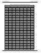
Table 2-1. Control Circuit Connector Pin-Outs
POWER SUPPLY PINS
P1-Z14 AGND
P1-D14 +24VDC
CH A RELAY PINS
ALARM 1
P1-D4 POLE
P1-B4 N.O.
P1-Z4 N.C.
ALARM 2
P1-D2 POLE
P1-B2 N.O.
P1-Z2 N.C.
CH A INPUT/OUTPUT PINS
P1-D12 OUT + A
P1-B12 OUT - A
P1-Z12 TEMP +A
P1-Z10 TEMP - A
P1-B14 SHIELD GND
P1-Z8 HTR + A
P1-B8 HRT RTN A
P1-D8 COM A
P1-D10 REF A
P1-B10 ACT A
P1-Z6 SHIELD GND
P1-D6 CHASSIS GND
CHANNEL A TEST CONNECTOR
P2-1 OUT +
P2-2 OUT -
P2-4 TEMP +
P2-8 TEMP -
P2-5 18V TEST POINT
P2-8 GND
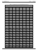
CH B RELAY PINS
ALARM 1
P1-D32 POLE
P1-B32 N.O.
P1-Z32 N.C.
ALARM 2
P1-D30 POLE
P1-B30 N.O.
P1-Z30 N.C.
CH B INPUT/OUTPUT PINS
P1-D18 OUT + B
P1-B18 OUT - B
P1-Z18 TEMP +B
P1-Z16 TEMP - B
P1-B16 SHIELD GND
P1-Z22 HTR + B
P1-B22 HRT RTN B
P1-D22 COM B
P1-D20 REF B
P1-B20 ACT B
P1-Z20 SHIELD GND
P1-D28 CHASSIS GND
CHANNEL B TEST CONNECTOR
P2-6 OUT +
P2-7 OUT -
P2-9 TEMP +
P2-8 TEMP -
P2-10 18V TEST POINT
P2-8 GND
Remote Mounting
1. Mount the control circuit rack to an appropriate and accessible surface. (See Figure 2-1.)
2. FCI's recommendation is to install conduit between the local enclosure and the remote enclosure, as well as
installing conduit between the remote enclosure and the power source and monitoring circuit. Provide water
tight hardware and apply thread sealant to all connections to prevent water damage.