INSTALLATION, OPERATION and MAINTENANCE MANUAL ™ ™ FLT Series FlexSwitch Flow, Level, Temperature Switch/Monitor with Rack Mount Control Circuit Doc. No. 06EN003250 Rev. N/C U.S. Patent 4,967,593 Notice of Proprietary Rights This document contains confidential technical data, including trade secrets and proprietary information which are the property of Fluid Components Intl (FCI).
FLUID COMPONENTS INTL CUSTOMER COMMITMENT PLEDGE We will work closely with our customers to provide the best products and service • at a competitive value • on time • with unquestioned support in full compliance with our COMPLETE CUSTOMER COMMITMENT.
FLUID COMPONENTS INTL CUSTOMER SERVICE/TECHNICAL SUPPORT FCI provides full in-house technical support for our products 7 a.m. to 5 p.m. PST, Monday through Friday (excepting holidays and an annual plant closure between Christmas and New Year's day). Also, additional technical representation is provided by FCI field representatives. Before contacting one of our field or in-house representatives, please ensure that you have performed the troubleshooting techniques outlined in this document.
FLUID COMPONENTS INTL FLT™ Series FlexSwitch™ Rack Mount iv Doc. No. 06EN0050 Rev.
FLUID COMPONENTS INTL Reserved for Domestic Rep Map Doc. No. 06EN0050 Rev.
FLUID COMPONENTS INTL Reserved for International Rep Map FLT™ Series FlexSwitch™ Rack Mount vi Doc. No. 06EN0050 Rev.
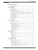
FLUID COMPONENTS INTL Contents Chapter 1 - General Information Description ....................................................................................................................................... 1 - 1 Theory of Operation ...................................................................................................................... 1 - 1 Technical Specifications ...............................................................................................................
FLUID COMPONENTS INTL Defective Parts ................................................................................................................................ 5 Spares ................................................................................................................................................. 5 Storage Information ....................................................................................................................... 5 Customer Service ............................
FLUID COMPONENTS INTL Symbols The following symbols are used throughout the manual to draw attention to items or procedures that require special notice or care. Warning: Warns of possible personal danger to those handling the equipment. Caution: Note: Cautions against possible equipment damage. Contains important information. Doc. No. 06EN0050 Rev.
FLUID COMPONENTS INTL FLT™ Series FlexSwitch™ Rack Mount x Doc. No. 06EN0050 Rev.
CHAPTER 1 - GENERAL INFORMATION FLUID COMPONENTS INTL 1. General Information Description The FLT Series uses FlexSwitch technology. The FLT Series models are multipurpose measurement instruments. They are individual instruments that are capable of detecting fluid flow and temperature. They are also able to detect liquid level or fluid interfaces. The instruments have two adjustable set-point alarms as well as a built-in calibration circuit.
APPENDIX D - TEMP COMP FLUID COMPONENTS INTL Appendix D. Temperature Compensation Introduction Temperature compensation (Temp Comp) is an essential part of the FLT FlexSwitch circuitry. When the Temp Comp is set correctly, the instrument stays accurate over a process temperature range of 100 °F. The instrument is a thermal dispersion device.
FLUID COMPONENTS INTL APPENDIX D - TEMP COMP 2. Write down where the heater wattage control jumper is located on the control circuit. Refer to Figure 3-1. Remove the heater wattage control jumper and install it in position J4 [J30] (heater off). Refer to Figure 3-1 for the jumper location. 3. Remove jumpers J1 and J2 [J27 and J28] from the control circuit and set them aside. 4. Connect the DMM from TP1 (next to J1) [TP3 (next to J27)] to the right jumper post of J1 [J27]. Set the DMM to ohms.
APPENDIX D - TEMP COMP FLUID COMPONENTS INTL Figure D-1. Potentiometer and Test Point Locations for Temp Comp Procedure 1. Turn off the instrument power. 2. Install the instrument into the pipe or a test stand where it can be calibrated. Start the process media flowing at a normal rate. Cool the process media to the lowest temperature in the expected operating range. 3. Disconnect the wires leading to the sensing element (ACT, REF, COM HTR, HTR).
FLUID COMPONENTS INTL APPENDIX D - TEMP COMP Figure D-2. Sensing Element Calibration Connections 6. Stop the process media flow and make sure that the media is at no flow and then let the instrument stabilize for fifteen minutes. 7. Record the resistance values of the sensing elements and calculate the resistance differential (∆R). If ∆R does not exceed the maximum ∆R of 280 ohms then proceed with the calibration.
APPENDIX D - TEMP COMP FLUID COMPONENTS INTL 15. If the calculated Temp Comp factor exceeds the allowable tolerance by a small amount (±0.01), using the maximum Temp Comp factor may make the instrument perform satisfactorily. However, if the factor is out of tolerance by more than ±0.01 then it will be necessary to repeat the calibration to verify the result. Continue with the adjustment procedure if the second result is within tolerance. Table D-2. Temp Comp Factor Table TEMP COMP FACTOR 0.042 0.041 0.
FLUID COMPONENTS INTL FLT Series FlexSwitch Rack Mount APPENDIX D - TEMP COMP D - 6 Doc. No. 06EN003250 Rev.
APPENDIX C - CUSTOMER SERVICE FLUID COMPONENTS INTL Appendix C. Customer Service Point of Contact Your point of contact for service, or return of equipment to FCI is your authorized FCI service representative (see list in the front matter of this manual). Reference Documents Return Authorization Request/Certificate of Non-Contamination (Document 1) FCI Hazardous Materials Control Procedure for Repair Items (Document 2) Warranties (Document 3) Documents 1, 2 and 3 are are included in this appendix.
FLUID COMPONENTS INTL APPENDIX C - CUSTOMER SERVICE Warranty Repairs or Returns FCI prepays ground transportation charges for return of freight to the customer’s door. FCI reserves the right to return equipment by the carrier of our choice. International freight, handling charges, duty/entry fees for return of equipment are paid by the customer. Nonwarranty Repairs or Returns FCI returns repaired equipment to the customer either collect or prepaid and adds freight charges to the customer invoice.
APPENDIX C - CUSTOMER SERVICE FLUID COMPONENTS INTL Document 1. Return Authorization Request/Certificate of Non-Contamination 1. Company Name: ____________________________________________________________________ 2. Contact Name: _____________________________________________________________________ 3. Contact Phone No. ________________________________ Fax No.: __________________________ 4.
FLUID COMPONENTS INTL APPENDIX C - CUSTOMER SERVICE Document 2. FCI Hazardous Materials Control Procedure for Repair Items In order for FCI to process your repair expeditiously, the returned item must be accompanied by documentation regarding hazardous materials to which the item was exposed. Hazardous materials are regulated by Federal, State (California), County, and City laws. These laws provide our employees the right to know the materials with which they come in contact while handling our products.
APPENDIX C - CUSTOMER SERVICE FLUID COMPONENTS INTL Document 3. Warranties Warranties Goods furnished by the Seller are to be within the limits and of the sizes published by the Seller and subject to the Seller’s standard tolerances for variations.
FLUID COMPONENTS INTL FLT Series FlexSwitch Rack Mount APPENDIX C - CUSTOMER SERVICE C - 6 Doc. No. 06EN003250 Rev.
APPENDIX B - GLOSSARY FLUID COMPONENTS INTL Appendix B.
FLUID COMPONENTS INTL FLT Series FlexSwitch Rack Mount APPENDIX B - GLOSSARY B-2 Doc. No. 06EN003250 Rev.
APPENDIX A - DRAWINGS FLUID COMPONENTS INTL Appendix A. Drawings Inch [mm] Figure A-1. Local Enclosure, NEMA Type 4X and Hazardous Location (Aluminum Enclosure Shown) Figure A-2. Local Enclosure NEMA Type 4X (Fiberglass Shown) FLT93-S CONFIGURATION FOR NPT AND FLANGE SENSING ELEMENTS FOR PACKING GLAND SENSING ELEMENTS FLT93-F CONFIGURATION FOR NPT AND FLANGE SENSING ELEMENTS FOR PACKING GLAND SENSING ELEMENTS Figure A-3. FLT93-S and FLT 93-F Sensing Element Configurations Doc. No. 06EN003250 Rev.
FLUID COMPONENTS INTL APPENDIX A - DRAWINGS Figure A-4. 1/4 (FLT-F Only), 3/4 or 1 Inch NPT Process Connection Figure A-5. Flanged Process Connection Figure A-6. Low Pressure Packing Gland FLT Series FlexSwitch Rack Mount A-2 Doc. No. 06EN003250 Rev.
APPENDIX A - DRAWINGS FLUID COMPONENTS INTL Figure A-7. Flanged Low Pressure Packing Gland Process Connection Figure A-8. 1-1/4 Inch Medium Pressure Packing Gland Connection Figure A-9. Flanged Medium Pressure Packing Gland Process Connection Doc. No. 06EN003250 Rev.
FLUID COMPONENTS INTL APPENDIX A - DRAWINGS ∅ .41 C00420-1 Figure A-10. 1/4 Inch Process Connection 3/4, 1 INCH NPT OR BSP PROCESS CONNECTION 2.0 [51]* *1 INCH NPT PROCESS CONNECTION HAS A 3 INCH [76] LONG THREADED LENGTH C00421-1 Figure A-11. Pigtail Process Connection C00423-1 Figure A-12. Injection Tube with Tee Fitting FLT Series FlexSwitch Rack Mount A-4 Doc. No. 06EN003250 Rev.
CHAPTER 5 - TROUBLESHOOTING FLUID COMPONENTS INTL 5. Troubleshooting Warning: Only qualified personnel should attempt to test this instrument. The operator assumes all responsibilities for safe practices while troubleshooting. Introduction In new or re-calibrated instruments, operating problems are most often caused by an improper installation. Review the information on instrument installation in Chapter 2 to verify correct mechanical and electrical installation.
FLUID COMPONENTS INTL CHAPTER 5 - TROUBLESHOOTING For Factory Calibrated Instruments, Check the Application Data Sheet (ADS) Design problems usually occur with first-time applications. If the Application Data Sheet does not match the instrument's actual process conditions, errors occur. See the plastic sleeve at the back of the manual for a copy of the ADS. 1. Review the instrument's ADS with plant operation personnel and plant engineers. 2.
CHAPTER 5 - TROUBLESHOOTING FLUID COMPONENTS INTL Table 5-2. Matrix of Nominal Resistance Values (ohms at 80°F) at P1 CH. B P1-B20 (ACT) P1-D22 (COM) P1-D20 (REF) P1-Z22 (HTR +) P1-B22 (HTR RTN) P1-B20 (ACT) 0 1.1K 2.2K OPEN OPEN P1-D22 (COM) 1.1K 0 1.1K 1.3K OPEN P1-D20 (REF) 2.2K 1.1K 0 2.4K OPEN P1-Z22 (HTR +) OPEN OPEN OPEN 0 110 S MODEL 560 F MODEL P1-B22 (HTR RTN) OPEN OPEN OPEN 110 S MODEL 560 F MODEL 0 Pin No.
FLUID COMPONENTS INTL CHAPTER 5 - TROUBLESHOOTING Problem Verify Power to Instrument Turn Power OFF, Remove Control Circuit Repair Field Wiring fail Check Continuity of the Field Wiring fail Verfify HTR & RTD Resist.
CHAPTER 4 - MAINTENANCE FLUID COMPONENTS INTL 4. Maintenance Warning: To avoid hazards to personnel, ensure that all environmental isolation seals are properly maintained. Introduction The instrument requires very little maintenance because there are no moving parts or mechanical parts subject to wear.
FLUID COMPONENTS INTL FLT Series FlexSwitch Rack Mount CHAPTER 4 - MAINTENANCE 4-2 Doc. No. 06EN0032250 Rev.
CHAPTER 3 - OPERATION FLUID COMPONENTS INTL 3. Operation Factory Default Configuration Unless a custom factory setup or calibration is specified, the FCI instrument is delivered in a standard factory default configuration. The standard configuration is shown in Table 3-1. Table 3-1. Standard Default Configuration Input Power 24VDC. Heater Power 0.75 Watts for air flow or liquid level applications (CH A, J5; CH B, J31). Numer of Alarms Two (CH A, J18; CH B, J44).
FLUID COMPONENTS INTL CHAPTER 3 - OPERATION Figure 3-1. 5495 Control Circuit Configuration Jumper Locations FLT Series FlexSwitch Rack Mount 3-2 Doc. No. 06EN003250 Rev.
CHAPTER 3 - OPERATION FLUID COMPONENTS INTL Table 3-2A. Selectable Heater Wattage Control Jumper CH A J7 J6 J5* J3* J4 Jumper CH B J33 J32 J31* J29* J30 FLT93-F Element (560 Ohm Heater) 0.57 Watts 0.52 Watts 0.49 Watts 0.20 Watts OFF FLT93-S Element (110 Ohm Heater) 3 Watts 1.75 Watts 0.75 Watts 0.27 Watts OFF *J5 and J31are standard for FLT93-S and J3 and J29 are standard for FLT93-F. Table 3-4. CH A Alarm Condition Conditions Flow/Level Switch Temp.
FLUID COMPONENTS INTL CHAPTER 3 - OPERATION Figure 3-2. Control Circuit Setup with Component Locations FLT Series FlexSwitch Rack Mount 3-4 Doc. No. 06EN003250 Rev.
CHAPTER 3 - OPERATION FLUID COMPONENTS INTL Balance Adjustment Under normal circumstances the control circuit balance procedure has been done by the factory. This procedure needs to be done by the customer if the control circuit or the sensing element have been replaced, the sensing element and control circuit are sent under separate cover, or extra cable is added between the control circuit and the sensing element. 1. Extend the circuit card on the circuit card extender. 2.
FLUID COMPONENTS INTL CHAPTER 3 - OPERATION Note: The calculated set point must be at least 0.020 volts greater than the normal signal to ensure that the alarm will reset. e) Slide the mode switch to the CAL position. f) Adjust the CAL potentiometer R27 (below the mode switch) until the voltmeter equals the calculated set point. g) For the appropriate alarm, determine whether the status LED is on or off (red for alarm 1 or green for alarm 2).
CHAPTER 3 - OPERATION FLUID COMPONENTS INTL Note: The alarm can be set for a specific flow rate. Follow the procedure above to step 7 except establish the specific flow rate rather than the normal flow. The output signal will be the set point value. Determine whether the alarm should actuate with decreasing or increasing flow and skip to the appropriate step 9.d) respectfully. Enter the specific flow rate value as the set point and follow the remaining steps.
FLUID COMPONENTS INTL b) CHAPTER 3 - OPERATION If the status LED is on, turn the set point adjustment potentiometer (R30 for alarm 1 or R29 for alarm 2) counterclockwise until the LED turns off and then slowly clockwise just until the LED turns on. Detecting Wet Condition (high level alarm) a) If the status LED is on, turn the set point adjustment potentiometer (R30 for alarm 1 or R29 for alarm 2) slowly counterclockwise just until the LED turns off.
CHAPTER 3 - OPERATION FLUID COMPONENTS INTL Detecting Increasing Temperature (high temperature alarm) a) Slide the mode switch to the CAL position. b) Adjust the calibrate potentiometer R27 (below the mode switch) until the voltmeter equals the normal temperature signal. c) For the appropriate alarm, determine whether the status LED is on or off (red for alarm 1 or green for alarm 2).
FLUID COMPONENTS INTL CHAPTER 3 - OPERATION Note: The output signal will vary inversely with changes in the process flow rate. The output signal level is also relative to the type of process media being measured. (See Figure 3-3.) 5. Establish the normal process flow condition and allow the signal to stabilize. 6. Record the normal flow signal value. Normal Flow Signal = ________ volts DC 7.
CHAPTER 3 - OPERATION FLUID COMPONENTS INTL Figure 3-3. Flow Application Signal Output e) Slide the mode switch to the CAL position. f) Adjust the calibrate potentiometer (R24) until the voltmeter equals the calculated set point. g) For the appropriate alarm, determine whether the status LED is on or off (red for alarm 1 or green for alarm 2). 1) If the LED is on, turn the set point adjustment potentiometer (R26 for alarm 1 or R25 for alarm 2) slowly counterclockwise just until the LED turns off.
FLUID COMPONENTS INTL CHAPTER 3 - OPERATION Note: The alarm can be set for a specific flow rate. Follow the procedure above to step 5 except establish the specific flow rate rather than the normal flow. The output signal will be the set point value. Determine whether the alarm should actuate with decreasing or increasing flow and skip to the appropriate step 7.d). Enter the specific flow rate value as the set point and follow the remaining steps.
CHAPTER 3 - OPERATION FLUID COMPONENTS INTL Detecting Dry Condition (adjustment with sensing element wet) Verify that the sensing element is wet. If the status LED is off, turn the set point adjustment potentiometer clockwise until the LED turns on. With the LED on, slowly turn the potentiometer counterclockwise one turn past the point at which the LED just turns off.
FLUID COMPONENTS INTL CHAPTER 3 - OPERATION Table 3-8. Temperature versus Voltage Output (sheet 1 of 5) T(°F) -100 -99 -98 -97 -96 -95 -94 -93 -92 -91 -90 -89 -88 -87 -86 -85 -84 -83 -82 -81 -80 -79 -78 -77 -76 -75 -74 -73 -72 -71 -70 -69 -68 -67 -66 -65 -64 -63 -62 -61 -60 -59 -58 0.00375 OHMS/OHMS/ C° 1000 OHMS PLATINUM TEMPERATURE VERSUS VOLTAGE OUTPUT, FLT93 V OUT T(°F) V OUT T(°F) V OUT T(°F) 1.434 -57 1.620 -14 1.804 29 1.439 -56 1.625 -13 1.809 30 1.443 -55 1.629 -12 1.813 31 1.447 -54 1.
CHAPTER 3 - OPERATION FLUID COMPONENTS INTL Table 3-8. Temperature versus Voltage Output (sheet 2 of 5) T(°F) 72 73 74 75 76 77 78 79 80 81 82 83 84 85 86 87 88 89 90 91 92 93 94 95 96 97 98 99 100 101 102 103 104 105 106 107 108 109 110 111 112 113 114 115 116 117 118 119 120 V OUT 2.169 2.173 2.177 2.181 2.186 2.190 2.194 2.198 2.202 2.207 2.211 2.215 2.219 2.223 2.228 2.232 2.236 2.240 2.244 2.248 2.253 2.257 2.261 2.265 2.269 2.274 2.278 2.282 2.286 2.290 2.295 2.299 2.303 2.307 2.311 2.315 2.320 2.
FLUID COMPONENTS INTL CHAPTER 3 - OPERATION Table 3-8. Temperature versus Voltage Output (sheet 3 of 5) T(°F) 268 269 270 271 272 273 274 275 276 277 278 279 280 281 282 283 284 285 286 287 288 289 290 291 292 293 294 295 296 297 298 299 300 301 302 303 304 305 306 307 308 309 310 311 312 313 314 315 316 V OUT 2.978 2.982 2.987 2.991 2.995 2.999 3.003 3.007 3.011 3.015 3.019 3.023 3.027 3.031 3.035 3.039 3.043 3.047 3.051 3.055 3.059 3.063 3.068 3.072 3.076 3.080 3.084 3.088 3.092 3.096 3.100 3.104 3.
CHAPTER 3 - OPERATION FLUID COMPONENTS INTL Table 3-8. Temperature versus Voltage Output (sheet 4 of 5) T(°F) 464 465 466 467 468 469 470 471 472 473 474 475 476 477 478 479 480 481 482 483 484 485 486 487 488 489 490 491 492 493 494 495 496 497 498 499 500 501 502 503 504 505 506 507 508 509 510 511 512 V OUT 3.760 3.763 3.767 3.771 3.775 3.779 3.783 3.787 3.791 3.795 3.799 3.803 3.806 3.810 3.814 3.818 3.822 3.826 3.830 3.834 3.838 3.842 3.845 3.849 3.853 3.857 3.861 3.865 3.869 3.873 3.877 3.880 3.
FLUID COMPONENTS INTL CHAPTER 3 - OPERATION Table 3-8. Temperature versus Voltage Output (sheet 5 of 5) T(°F) 660 661 662 663 664 665 666 667 668 669 670 671 672 673 674 675 676 677 678 679 680 681 682 683 684 685 686 687 688 689 690 691 692 693 694 695 696 697 698 699 700 701 702 703 704 705 706 707 708 V OUT 4.512 4.516 4.520 4.523 4.527 4.531 4.535 4.538 4.542 4.546 4.550 4.554 4.557 4.561 4.565 4.569 4.572 4.576 4.580 4.584 4.587 4.591 4.595 4.599 4.602 4.606 4.610 4.614 4.617 4.621 4.625 4.629 4.
CHAPTER 2 - INSTALLATION FLUID COMPONENTS INTL 2. Installation Receiving/Inspection • • • Unpack carefully. Verify that all items in the packing list are received and are correct. Inspect all instruments for damage or contaminants prior to installation. If the above three items are satisfactory, proceed with the installation. If not, then stop and contact a customer service representative. Packing/Shipping/Returns These issues are addressed in Appendix C - Customer Service.
FLUID COMPONENTS INTL CHAPTER 2 - INSTALLATION Verify Flow Direction and Placement Orientation for the Sensing Element (Flow Application) For flow detection, the sensing element surface marked with direction arrows should be oriented parallel to the process flow . The flow can be from either direction. See the appropriate figure in Appendix A for the flow arrow marking. For liquid flow service, the sensing element should be located in the process pipe so that the thermowells are always completely wet.
CHAPTER 2 - INSTALLATION FLUID COMPONENTS INTL Control Circuit Wiring Mount the control circuit remotely by following the procedure below. Warning: Ensure that all power is OFF before wiring any circuit. Wiring The input/output connector for the control circuit is a 48 pin type F Eurocard connector, (DIN 41612). Shielded cable must be used when running the cables to the sensing elements, as well as the signal voltage outputs if they are used. Refer to Table 2-1 for the pin designations. Table 2-1.
FLUID COMPONENTS INTL CHAPTER 2 - INSTALLATION 3. Install 5 connector shielded cable (factory or customer supplied) between the sensing element and the control circuit. Refer to Figure 2-1 or 2-2 for connection information. 4. Ensure the specified operating power is supplied to the control circuit. Refer to Figure 2-1 or 2-1 for connection information.
CHAPTER 2 - INSTALLATION FLUID COMPONENTS INTL Figure 2-1. Wiring Diagram: Remote Mounting Doc. No. 06EN003250 Rev.
FLUID COMPONENTS INTL CHAPTER 2 - INSTALLATION Figure 2-2. Wiring Diagram: Remote Pig Tail FLT Series FlexSwitch Rack Mount 2-6 Doc. No. 06EN003250 Rev.
Fluid Components Intl ERRATA 17EN000019 Rev. A ERRATA DESCRIPTION Appendix E is added for the CE mark. Also a wire length Table is added to the installation. See the following information. Appendix E.
ERRATA 17EN000019 Rev. A Fluid Components Intl INSTALLATION CONFORMITY CRITERIA Grounding All enclosures must be grounded to earth ground through a path of less than 1 ohm. Interconnecting Cables All interconnecting cables between the FlexSwitch local enclosure, remote enclosure, power source and monitoring device shall be enclosed in metal conduit. Standard ESD Precautions Use standard ESD precautions when opening an instrument enclosure or handling the FlexSwitch.