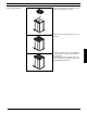
Fluid Components Intl 5. Installation of Transmitter 5.1 Compact (Integral) IP 67 version Remove and discard the terminal box cover of the sensor. 1 Fit the Pg 13.5 cable glands for the supply and output cables. (13.5 X 1/2 NPT adapters are supplied with each unit. FCI part number 017945-01). 2 Please see the wiring diagram for the "Electrical connections". 3 Document 06EN003327 Rev. - Mount the signal converter on the terminal box. 31 FlexCOR™ Model CMF Series Installation of signal con.
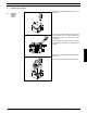
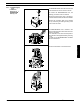
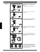
Fluid Components Intl 1. Remove the outer frame using a fingernail or a screwdriver. Turning the control pad 2. Loosen the 4 screws retaining the control pad. 3. Withdraw the control pad and turn it to the required orientation. 1 4. Tighten the 4 screws until a mechanical stop is felt in order to obtain IP 67 enclosure rating. Installation of signal con. 5. Snap-lock the outer frame onto the control pad (click).
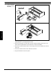
Fluid Components Intl 5.2.1 Add-on modules Unpack the add-on modules and locate it in the bottom of the transmitter as shown. The add-on module has now been installed. The transmitter is ready to be installed on the terminal box. Communication to the operator menu and electrical inputs and outputs are automatically established at power on. Document 06EN003327 Rev. - 33 FlexCOR™ Model CMF Series Installation of signal con. Press the add-on module forward as far as possible.
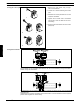
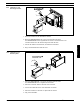
Fluid Components Intl 5.2.2 Remote installation Wall mounting Compact (Integral) IP 67 version Mount the wall bracket on a wall, pipe or in the back of a panel. Installation of signal con. Take the SENSORPROM® unit from the sensor. Mount the SENSORPROM® unit in the wall mounting unit as shown. The labelon the SENSORPROM® unit must face the wall bracket. Mount the connection plate in the terminal box. Tighten the earth ground screw in the center of the connection box properly.
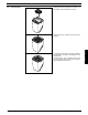
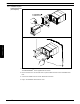
Fluid Components Intl 5.2.3 Compact(Integral) IP 67 Installation/ exchange of SENSORPROM® memory unit The SENSORPROM® unit is delivered mounted in the terminal box of the sensor as shown. 1 To remove the SENSORPROM® unit, the following procedure must be followed: Remove the terminal box cover of the sensor, or remove the transmitter, if it has been installed. 2 The SENSORPROM® unit is located in the bottom of the terminal box and can be removed. Note the orientation.
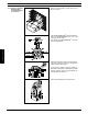
Fluid Components Intl Installation of signal con. 5.2.4 Remote installation Signal converter in 19" insert 1. Fit the SENSORPROM® unit on the connection board supplied with the transmitter. The SENSORPROM® unit is supplied with the sensor. 2. Mount the guide rails in the rack system as shown. Distance between guide rails is 21 TE. Guide rails are supplied with the rack system and not with the transmitter. 3. Mount the connection board as shown.
Fluid Components Intl 5.2.5 Installation in wall mounting enclosure 1. Mount the enclosure to the wall with four screws. 3. Connect the cables to the terminals, see "Electrical connection". 4. Plug in the transmitter and close the cover. 5.2.6 Installation in the back of a panel 1. Mount the SENSORPROM® unit on the connection board as shown. The SENSORPROM® unit is supplied with the sensor. 2. Mount the connection board in the back of the enclosure. 3.
Fluid Components Intl Installation of signal con. 5.2.7 Installation in panel mounting enclosure (front of panel) 1. Mount the SENSORPROM® unit on the connection board as shown. The SENSORPROM® unit is supplied with the sensor. 2. Fit the enclosure in a cut out at the front of a panel. Fasten the four screws accessible at the front. 3. Connect the cables as shown under "Electrical connection". 4. Plug in the transmitter and close the cover. FlexCOR™ Model CMF Series 38 Document 06EN003327 Rev.
Fluid Components Intl Unpack the add-on module and locate it in the bottom of the transmitter as shown. 5.2.8 Add-on modules The add-on module has now been installed and the transmitter is ready to be installed on the terminal box. Communication to the operator menu and electrical inputs and outputs are automatically established by power on. Document 06EN003327 Rev. - 39 FlexCOR™ Model CMF Series Installation of signal con. Press the add-on module forward as far as possible.
Fluid Components Intl For compact (integral) installation mount the transmitter on top of the sensor interface. Make sure that it is correctly oriented (note the little tag). After placement, it can be turned 0-360°. 5.2.9 Compact Ex-d version The transmitter is secured with 4 allen screws (allen key M4). Installation of signal con. The terminals for inputs, outputs and power supply can be accessed by removing the front cover, turning it counter-clockwise. The display can be lifted off (i.e.
Fluid Components Intl 5.2.10 Remote installation of multiple plug at the sensor For remote installation mount the adaptor on top of the sensor interface. If not already mounted. When fitting the multiple plug, please make sure that it is correctly oriented (note the little tap). The adaptor can be oriented in 4 directions. Tighten the 4 screws with a 4 mm allen key to secure the adaptor. Mount the multiple plug in the adaptor and tighten the glands on the plug to obtain optimum sealing.
Fluid Components Intl 5.2.11 Compact (Integral) Ex-d version Location of the SENSORPROM® memory unit The SENSORPROM® unit is normally factory-installed. To remove the SENSORPROM® unit, use the following procedure: 1. Remove the rear cover, by loosening the safety tap allen screw (M3), and turn the rear cover counter-clockwise. 2. Remove the electronics using the holes provided. Installation of signal con. The SENSORPROM® unit is placed at the bottom of the housing.
Fluid Components Intl 5.2.12 Compact (Integral) Ex-d version Installation of add-on module Remove the rear cover, by loosening the safety tap allen screw (M3) and turn the rear cover counter-clockwise. Remove the electronics using the holes provided. Remove the plate from the module bay. The add-on module is fitted at the bottom of the converter insert as shown. The label text on the add-on module should face up as shown. The add-on module is fitted with the connector facing out of the enclosure.
Fluid Components Intl When installing the add-on module in the Transmitter Ex-d, only Ex modules which have been approved can be used. Warning Ex-compliance of add-on module All modules, which can be used, have been clearly marked with the Ex-symbol and Ex-approval No. Installation and wiring, instructions supplied with the module must be followed. If the electronics is to be replaced or an add-on module is to be installed, this can be done by dismantling the cover located in the back of the enclosure.