
User guide

FLUID COMPONENTS INTL CHAPTER 1 - GENERAL INFORMATION
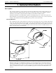
Model 12-64 Basic Flow Switch
1 - 2
Doc. No. 06EN003264 Rev. N/C
• Service:
- 12-64 - Liquid, gas or slurry flow detection.
- 8-66 - Point liquid level or interface detection.
• Process Connections:
1 inch male NPT.
• Insertion Length:
1.2 inch (30mm) or 2.0 inch (51mm) U-length.
• Material of Construction:
All wetted surfaces are 316 series stainless steel with
nickel braze per process specifications AMS 4777.
• Alarm Set Points:
Setable to any value within the indicated flow range,
(for 12-64). Setable to anyinterface value, (for 8-66).
5mV hysteresis.
• Time Response:
10 to 300 seconds.
• Flow Rate (12-64 only):
Minimum: .010 ft/sec (.003 m/sec) in oil,
Maximum: 125 ft/sec (38 m/sec) in air.
• Electrical Connection:
1 inch female NPT
• Relay Rating:
DPDT contacts rated at 2A at 115 Vac.
• Power Input:
100-132 Vac, 50/60 Hz, 6 watts maximum. 230 Vac
or 24 Vdc are optional power inputs.
• Local Enclosure:
NEMA 4X (approximately equal to IP66) and
suitable for hazardous locations.
• Operating Temperatures:
Sensing element: -100° to +350°F (-73° to +177°C).
Control circuit: -40° to +140°F (-40° to +60°C).
• Operating Pressure:
To 3000 psig (207 bar).
• Approvals:
FM, CSA and CE / CENELEC.
Control Circuit
The basic functions of the control circuit are to provide power to the sensing element, measure the DR between the
two RTDs, condition the sensing point signals, and provide relay alarm contacts for customer uses.
A double pole double throw (DPDT) relay is available in the instrument for connections to the customer alarm
systems. The relay coil can be set for either energized or de-energixed when there is either flow (wet) or no flow
(dry) of the process media. [The factory set condition is the coil being de-energized at no-flow (dry).]
The place where the relay changes state will vary depending on the type of media as well as air or liquid turbulence.
Therefore the instrument has a field adjustable alarm set point.
Specifications