
Reference


Components
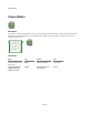
Clip
Description
When you draw onto a View you draw inside a region called the Clipping Area. By default the clipping area of a View is defined by the
bounding area of the module panel to which it applies.
The clipping area can be changed by applying one or more Clip components in sequence. Each Clip modifies the current clipping area by
applying another area according to a particular clipping mode. The clipping modes are as follows:
0
Intersect The clipping area becomes the intersection of the current clipping area
and the new area
1
Union The clipping area becomes the areas covered by the current area and
the new area
2
Complem
ent
The clipping area becomes the part of the new area that does not
intersect with the current clipping area
3
Exclude The clipping area becomes the area covered by the current area but not
the new area
4
Xor The clipping area becomes the areas covered by the current area or the
new area, but not both
Connectors
Inputs Type Outputs Type
Source View
View View with modified
clipping
View
Area to apply to clipping
Area
Clipping mode
Int
53 of 494