
Reference

Components
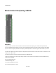
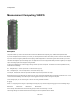
Measurement Computing 1608FS
Description
This primitive allows you to send and receive data to and from the Measurement Computing Corp. 1608FS data acquisition board.
If you have multiple boards connected to your PC then you should provide the number of the board you want to connect to at the 'Board'
input. This number is assigned by Measurement Computing's InstaCal application so refer to that to get the board number if you need it.
The board has 8 digital I/O pins and 8 analog inputs. The digital I/O can each be configured individually as either a digital input or a digital
output. The analog inputs are all configured as single ended.
To set the I/O configuration you need to supply a string to the I/O input of the component. This should be a comma separated list of any
combination of the following:
DIn - set digital I/O pin n to be an input where n is the index of the pin (0-7)
DOn - set digital I/O pin n to be an output where n is the index of the pin (0-7)
For example, “DI2,DO4,DI5” would use pins DIO2 and DIO5 as inputs and pin DIO4 as an output.
Note that the I/O string only alters what you specify in the list. If you don't specify what DIO3 does for example it will remain as it is – it will
not be reset to default settings. Also note that you need to trigger the Set input in order for changes to take place.
For the analog inputs you can set the ranges. To do this use a string formatted as follows:
Rn=[type]
Where n is a single digit in the range 0-7 representing the analog I/O pin you want to configure and [type] is one of the following strings:
BIP1VOLTS BIP2VOLTS BIP5VOLTS BIP10VOLTS
So for example, "R2= BIP5VOLTS" would set analog input pin CH2 IN to use the range +/-5 volts.
These range settings are combined with the other I/O settings as comma separated values as before.
204 of 494