
Reference
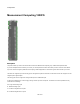
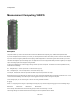

Components
AO - set bank A of digital I/O to be outputs
BO - set bank B of digital I/O to be outputs
For example:
“SE,AI,BO” would use single ended analog, bank A as digital inputs and bank B as digital outputs.
“D,BI” would use differential analog and bank B as digital inputs.
Note that the I/O string only alters what you specify in the list. If you don't specify what bank A does it will remain as it is – it will not be reset
to default settings.
Also note that you need to trigger the Set input in order for changes to take place.
When using differential analog inputs you can set the ranges. To do this use a string formatted as follows:
R[n]=[type]
Where [n] is a single digit in the range 0-3 representing the analog I/O pin you want to configure
and [type] is one of the following strings:
BIP20VOLTS BIP10VOLTS BIP5VOLTS BIP4VOLTS BIP2PT5VOLTS
BIP2VOLTS BIP1PT25VOLTS BIP1VOLTS
So for example, "R2= BIP5VOLTS" would set analog input pin number 3 (so at index 2) to use the range +/-5 volts.
These range settings are combined with the other I/O settings as comma separated values as before.
For example, "AI,BO,R2= BIP5VOLTS".
Note that cbw32.dll must be installed on the host system for this component to work. If you have installed the Measurement Computing
drivers then this file should be on your system.
203 of 494