
Reference
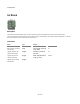
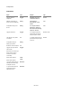

Components
To set the I/O you need to trigger the Set input below the I/O String input.
For example:
“DO4, DO5, AI6, AI7-SP, AI8-6” would make pins 4 and 5 digital outputs. Pins 6,7 and 8 would all be analog inputs with 6 being single
ended, 7 using the special 0-3.6v range and 8 using input 6 as a negative channel.
Timers and Counters
The U3 has two timers and two counters that you can use. The timers and counters take over the flexible I/O. You specify a start pin and
then depending on the number of timers and counters you use the pins from this start pin onwards will be used as timers or counters.
You can set the number of counters via the Counters input.
The timers are set using a configuration string. This is similar to the I/O specification in that it's a comma separated list of parameters (or a
newline separated list if you use a Text component).
The timer configuration string is in the form
{number of timers} {clock{/divisor}} {mode timer0} {value timer0} {{mode timer1} {value timer1}}
Clock values can be 4, 12 or 48 MHz and can include a divisor as well. There is also a 1 MHz clock which must include a divisor. This gives
7 possible clock value strings:
1MHz/{divisor} , 4MHz/{divisor} , 12MHz/{divisor} , 48MHz/{divisor} , 4MHz , 12MHz or 48MHz.
Where {divisor} is an integer in the range 0-255.
Modes are strings and map onto the U3 modes exactly. They can be one of the following:
PWM16, PWM8, RISINGEDGES32, FALLINGEDGES32, DUTYCYCLE, FIRMCOUNTER, FIRMCOUNTERDEBOUNCE, FREQOUT, QUAD,
TIMERSTOP, SYSTIMERLOW, SYSTIMERHIGH, SYSTIMERHIGH, RISINGEDGES16 or FALLINGEDGES16.
Some examples:
“1,48MHz,FREQOUT,128" – a single timer, clock 48MHz using the Frequency Output method
“2,4MHz/200,PWM16,32768,PWM8,16384" – two timers, clock 48MHz with divisor 200
To set the timer and counter configuration trigger the Set unput below the Counters input on the component.
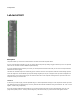
Because the timers and counters take over some of the flexible I/O pins you should see the outputs on the component corresponding to
those pins change to Integer connectors labeled TIM0, TIM1, CTR0 or CTR1.
Note that when using a clock with a divisor the LabJack U3 only allows you to use 1 counter.
The U3 has two DACs you can set the value of these using the DAC0 and DAC1 inputs on the component.
You can reset a timer or counter by sending the appropriate index value to the Reset input. Send 1 or 2 to reset the 1
st
or 2
nd
timer and 3 or 4
to reset the 1
st
or 2
nd
counter.
For more information on the workings of the U3 see the U3 user guide.
186 of 494