
User manual

- 7 -
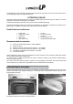
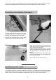
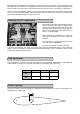
If you choose gas engine, so fix the tank instead
of the battery with velcro tapes. We recommend
to use an anti-slide map under the tank or even
under the battery.
For resonance exhaust systems the kit contains
two kinds of frames (55 mm and 65 mm).
The frames should be glued into the exhaust tun-
nel.
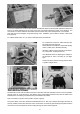
For some types of one cylinder engines it is ne-
cessary to install the gas servo beside the motor
dome. The laser cutten parts for this servo frame
are also content of the model kit.
Rudder linkage:
The rudder linkage is conventionally realized with
2 steel ropes. The set force of the rudder servo
should be above 200 Ncm.
(MKS DS 660A+, Order No.: 007-660)
The ropes should be installed crosswise, because
the outlet angel is better.
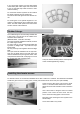
On servo side you can use the linkage balls with
eye bolts or linkage balls - eye bolts and rope
tension bolts.
We only used eye bolts together with the linkage
balls.
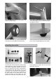
The rope should be threaded into the eye bolts.
Then put the brass sleeve over both ropes and
make an additional loop through the sleeve. Now
crimp the brass sleeve with a crimping tool. Cover
the crimped rope with a shrinking tube.
Crimp the sleeve carefully that the steel rope be-
comes not damaged during crimping.
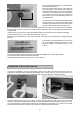
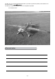
Installing the elevator servos:
For elevator servos we recommend standard servos with a setforce of 100Ncm. The Flitework FW-4020M
would be a good choice. It is strong, quick, exactly, has coreless motor and a nice price. (007-4020M)
Screw the servo like picture into the servo shaft.
Use a 1,5 mm drill to make holes for the screws.
Attach the servo lever extension to the round servo
plate.
Use a servo tester to bring the servo into neutral
position. Then screw the servo lever onto the
servo. Use blue locking agent to fix the screw.
Next step is the mounting the lever system to the
elevator flaps.
A box column drill is very useful.