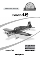
Instruction manual ...
Technical data: · Wingspan · Length · Wing area without elevator · Take off weight with 12s5000 and Flitework TB-5000 · Electric power system · Gas engine -2- 2600 mm 2400 mm 112 dm² 10.
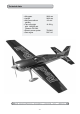
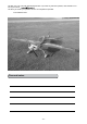
Congratulations for purchasing the Flitework Extra 300LPX. We say thanks for your trust and we wish you a lot of happy flights with your new Extra 300 LPX. ATTENTION PLEASE! Remote controlled model planes are not a toy! For assembling, flying and servicing such models, you need a high grade of technical comprehension and liability. Careless assembling and operation may cause personal and material damage.
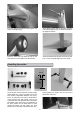
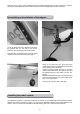
To fit the fairings with adhesive tape against the body is normally enough. Screw the wheel hub into the gear bow and take care, that the edges of the hex head are parallel to the edges of the bow. Place the wheel with the adjusting rings on the shaft, that it is in the middle of the wheel pants. Screw the wheel pants with M3 screws to the gear bow. Look for a parallel alignment of the pants! Installing the rudder: 8mm 28mm During glueing the hinges, look for the correct adjustment of the axis.
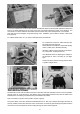
Take care, that no glue comes inside the hinges. Be careful especially with PU glue, because its volume is growing up during hardening. Glue inside the hinges becomes a big problem for their movement. Assembling and installation of the tailgear: Screw the aluminium bow of tail gear to the tail of the fuselage like you can see on the picture. Therefore you should use 3 mm wood screws. Assemble the mechanical parts of the tail wheel hub and fix all screws with blue locking agent.
Cut out the template from the end of this manual. Use adhesive tape to fix the template against the firewall and look for an exactly adjustment of the cross mark. This cross mark indicates the center of the driveline. The cross mark is not in the middle of the firewall, because a basic side pull is already built in, in the firewall. This side pull can be enlarged, using shims during motor installation. (The model kit contains a few Shims from plywood).
If you choose gas engine, so fix the tank instead of the battery with velcro tapes. We recommend to use an anti-slide map under the tank or even under the battery. For resonance exhaust systems the kit contains two kinds of frames (55 mm and 65 mm). The frames should be glued into the exhaust tunnel. For some types of one cylinder engines it is necessary to install the gas servo beside the motor dome. The laser cutten parts for this servo frame are also content of the model kit.
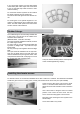
Put the flap with blue side below on the table of the box column drill machine. Place the aluminium laver base 41 mm away from the inside edge of the elevator flap. Mark the drilling side with a marker. Then you can make the 5 mm hole. If you dont like to see any screw parts on the upper side of the flap you should stop drilling about 0.3 mm before reaching the film on the opposite side. 41mm Cut off the head of the M5 screw and glue the bolt into the hole, using a very good epoxy glue.
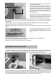
Very important is the adjustment of the linkage of both aileron servos. Very useful is a servo tester which can indicate the current of the servos. For adjustment put the wing into vertical position. Adjust the linkages of both servos so, that the no-load current of the servos becomes a minimum. Use a 4 mm wrench for adjustment. Servos, which are not adjusted correctly, have a lot of power consumption and a lot of stress.
We wish you a lot of fun with this Flitework model. If you have any technical question, dont hesitate to contact us per mail to: We will try to answer your question as soon an competent as possible.
Template for TB-5000 Template for DLE111 - 11 -
Flitework GmbH Tel: +43 720 5154 01 Geymannstraße 27 4713 Gallspach Austria / Europe Fax.:+43 720 5154 09 Mail.: office@flitework.