
Installation Guide

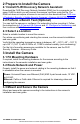

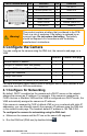
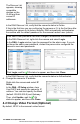
Table Of Contents

CP-6408-21-I QIG Rev 130
May 2021
This document does not contain any export-controlled information.
14-Pin Terminal Block
Pin
Definition
Pin
Definition
1
Audio-Out
8
RS-485 D-
2
Ground (Audio I/O)
9
Alarm-In 4
3
Alarm-Out A1
10
Alarm-In 3
4
Alarm-Out A2
11
Alarm-In 2
5
Alarm-Out B1
12
Alarm-In 1
6
Alarm-Out B2
13
Ground (Alarm I/O)
7
RS-485 D+
14
Audio-In
Warning!
This product contains a battery that is soldered to the PCB.
There is a risk of explosion if the battery is replaced by an
incorrect type. Do not replace the battery. The battery
should be disposed of in accordance with the battery
manufacturer’s instructions.
4 Configure the Camera
You can configure the camera using the DNA tool, the camera's web page, or a
VMS.
DNA tool
Camera's web page
Discover camera IP address
•
Configure IP address, mask, and gateway
•
•
Configure DNS settings, MTU, and Ethernet speed
•
Change user credentials
•
•
Change video format
•
•
Configure more than one camera at the same time
•
For more information about using a VMS to configure one or more cameras at the
same time, see the VMS documentation.
4.1 Configure for Networking
By default, DHCP is enabled on the camera and a DHCP server on the network
assigns the camera an IP address. For example, if the camera is managed by
FLIR's Horizon or Meridian VMS and the VMS is configured as a DHCP server, the
VMS automatically assigns the camera an IP address.
If the camera is managed by FLIR’s Latitude VMS or is on a network with static IP
addressing, you can manually specify the camera’s IP address using the DNA tool
or the camera's web page. The camera's default IP address is 192.168.0.250.
To configure the camera for networking using the DNA tool:
a. Make sure the camera and the PC are on the same LAN segment.
b. Run the DNA tool (DNA.exe) by double-clicking .