
Installation Guide


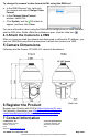
Table Of Contents

CP-6408-21-I QIG Rev 130
May 2021
This document does not contain any export-controlled information.
3.4 Connect the Camera
Connectors
Connector
Connection
1
DC12V IN
If using a 12 VDC power supply, connect its wires to the
two-pin power connector. See pin assignment below.
Do not use the DC12V IN and AC24V IN
connectors at the same time.
2
LAN
Attach a Cat 5e or Cat 6 cable from the network switch
to the RJ45 connector for a 10/100/1000 Mbps Ethernet
and PoE connection. If using PoE, use a FLIR CP-POE-
4P-60W-xx injector or a switch that supports Universal
PoE 60W 4 pair forced mode. For more information
about compatible injectors and recommended switches,
contact FLIR support. Verify that the LAN connector
LEDs are steady green and flashing yellow.
3
AC24V IN
If using a 24 VAC power supply, connect it to the three-
pin power terminal block according to the pin
assignment shown.
Do not use the DC12V IN and AC24V IN
connectors at the same time.
4
DEFAULT
To reset factory defaults at any time, press the Default
button for at least 20 seconds.
5
14-pin
terminal
block
Attach wires from external devices to the 14-pin terminal
block connector for alarm and audio in/out according to
the pin assignment shown.
6
VIDEO
BNC connector for analog video output.
DC12V IN
Connector
Pin
Definition
1
-12 VDC
2
+12 VDC
AC24V IN Connector
Pin
Definition
1
AC 24L
2
Ground
3
AC 24N