Ranger® R Series Radars Mid-Range Perimeter Surveillance Radar Operator Manual R1, R2, R3, R3D, R5, R5D, R4SS-X, R6SS-X, R8SS-X & R20SS FLIR Radars Inc. 4176 Boul. Industriel Laval, QC H7L 6H1 : +1(450) 662.7557 : radars@flir.com www.flir.com Document Number: 910-0001-00-MAN Issue Date: March 2019 Version: R06 This document is proprietary to FLIR Radars Inc.
©2019 FLIR Radars Inc. Reference #910-0001-00-MAN-R06 This documentation is provided as a component of the FLIR Radars Inc. All parties or individuals who are in possession of the documentation accept in full and without exception or limitation the FLIR Radars Inc. unrestricted rights of ownership of this material. This documentation is not available by any other means except by license which is only available from FLIR Radars Inc.
CONTACT INFORMATION Toll Free North America 1.866.657.4554 +1(450) 662.7557 +1(450) 622.7134 www.flir.com radars@flir.
REVISION RECORD TABLE Manual Revision ECO # Pages Description of Modification 1.0 13-008 All PSR Software Version 6.1.0 All Insertion of ITAR statement 2.0 3.0 14-001 All Add "FLIR Proprietary Information" to footer 4.0 16-025 All Added information for R6SS and R6SS-U 5.0 18-010 All Added 3D, updated R6 variants 6.
The following symbols are used throughout this document: Caution! The CAUTION symbol is used to alert the reader to situations where a hazard to personnel safety may arise. WARNING! The WARNING symbol is used to alert the reader to situations where equipment damage is imminent if a recommended process is not followed or alert the reader of a process that will alter or reset current configuration of a specific setup.
DEFINITIONS AND ACRONYMS AXML BIT CE CFAR Doppler Amphitech eXtensible Markup Language Built-in Test Refers to CE marking, a conformity mark in Europe Constant False Alarm Rate Doppler effect. Also refers to Doppler radar operation mode, where target speed is used to reject fixed clutter.
TABLE OF CONTENTS 1 INTRODUCTION ........................................................................................ 11 1.1 SAFETY ISSUES ......................................................................................... 11 2 PSR SYSTEM OPERATION ............................................................................. 13 2.1 2.2 RADAR APPLICATION MANAGER ...................................................................... 13 2.1.1 Application Status ...................................
LIST OF FIGURES Figure Figure Figure Figure Figure Figure Figure Figure Figure Figure Figure Figure Figure Figure Figure Figure Figure Figure Figure Figure Figure Figure Figure Figure Figure Figure Figure Figure Figure Figure Figure Figure Figure Figure Figure Figure Figure Figure Figure Figure Figure Figure Figure Figure 1 - Radar Application Manager Main Window............................................................... 2 - Login Operator Mode ..........................................................
Figure Figure Figure Figure Figure Figure Figure Figure Figure Figure Figure Figure Figure Figure Figure Figure Figure Figure Figure Figure Figure 45 46 47 48 49 50 51 52 53 54 55 56 57 58 59 60 61 62 63 64 65 - Track Recovery Enable Parameter ...................................................................... - Tracks Being Coasted ...................................................................................... - Track Being Recovered .............................................................
LIST OF TABLES Table Table Table Table Table Table 1 2 3 4 5 6 - Radar Console Functions vs. Login Level ................................................................. - Radar Icons and Messages .................................................................................. – PPI Commands ............................................................................................... - Configuration Parameters Groups .........................................................................
1 INTRODUCTION This manual describes the Perimeter Surveillance Radar (PSR) system operation. The Operator Manual is intended for an audience of technically qualified personnel. For installation and configuration of the radar system, or for more advanced functions, please refer to the installation manual of your specific radar. Note Please note that the generic product name “radar” is used throughout this manual for ease of reading.
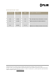
R5D (921-0031-02-R04) (FastScan) R5D (921-0031-02-R04) (Doppler) 0.56 Watt Ka 13 28 0.56 Watt Ka 25 55 Note: theses distances are for guidance only DISPOSAL This product contains a lithium battery. Dispose in accordance with the laws and regulations applicable in your jurisdiction. WARNING! The R4SS-X/R6SS-X/R8SS-X/R20SS pan/tilt positioner contains moving parts that can pinch fingers and/or other body parts. Use caution when the pan/tilt positioner is powered on.
2 PSR SYSTEM OPERATION This section covers the operation of the PSR Radar System using the Radar Console Application. For details on how to perform radar installation, please refer to the installation manual of your specific radar. For details on how to perform radar configuration, please refer to the Configuration Manual. WARNING! All the FLIR radars are intended for outdoor use only.
2.1.1 Application Status The application status will read either ACTIVE, UNLINK or TIMEOUT. An ACTIVE application is monitored by the Application Manager and will automatically re-start in the event of a crash, power outage or system failure. An UNLINK status reflects an application started manually and that is not monitored by the Application Manager. If the application closes or hangs, the Application Manager will not re-start it.
2.2 RADAR CONSOLE The Radar Console allows the configuration of radar assemblies, the configuration of detection and intrusion zones, and the visualization of radar sectors, targets and intruders. 2.2.1 Operator Login This application requires the user to login to access most of its functions, as shown in Figure 2. Four (4) login levels are supported by Radar Console. This document covers the two (2) first levels (Operator and Administrator).
Table 1 shows the functions that are accessible according to the login level. The Direct column refers to functions accessible when the Radar Console is connected directly to the radar, and the Server column refers to functions accessible when the Radar Console is connected to the radar via the Radar Server.
Dialog Right mouse click on radar icon Set radar to XMIT / STBY x x Reset radar x x Configure radar parameters x x x x Set unit position from GPS x x Set Radar Server time from GPS x Enable / disable ICD-0100 x Enable / disable AXML x Record targets / intruders x Record radar data x x Reset communication statistics x x Loader x Table 1 - Radar Console Functions vs. Login Level 2.2.1.
Figure 4 - Radar Lexicon Radar Icon Message Radar communication link is being established. Radar connection is in progress. Radar is in standby mode. Radar simulator is in standby mode. Track Combination Software is stopped. Radar is in standby mode, and is connected directly to the Radar Console application (instead of being connected through the Radar Server application).
Communication with radar has been interrupted for at least five (5) seconds. Communication with radar is lost. The Operator can still verify the last unit configured parameters and most recent unit warnings. The Operator can manually delete the lost icon. Radar is in limited auto-recovery mode, with failure code 5.60. The Radar will try to recover from the failure automatically. Radar is in fail mode, with failure code 5.60.
The Radar Console is recording data from this radar. The radar possesses an embedded GPS receiver which cannot have a 3D position fix. The radar is in standby mode. The radar possesses an embedded GPS receiver which has a 3D position fix. The radar is in standby mode. The radar possesses an embedded GPS receiver which cannot have a 3D position fix. The radar is in transmit mode but there is no synchronization with the GPS PPS signal. The radar possesses an embedded GPS receiver which has a 3D position fix.
When right-clicking with the mouse over the radar icon, a menu displays as follows: Figure 5 – Radar Control When placing the mouse cursor over the radar icon, a radar information box displays as follows: Figure 6 - Radar Information 910-0001-00-MAN-R06 FLIR Proprietary Information Page 21 of 81 Information contained in this document pertains to a Canadian origin product that is controlled as "dual use" by the Canadian government.
2.2.2 Radar Mode Change (applies only to R3D and R5D radars) The R3D and R5D supports a non-Doppler mode, the FastScan mode, and three Doppler modes (short, medium and long time-on-target). Changes of mode, range or time-on-target are made by using an icon and a drop-down list in Radar Console, as shown in Figure 7 and Figure 8. The toggle button (Figure 7) allows the user to conveniently switch between FastScan and Doppler modes.
Figure 8 - Changing Range and Time-On-Target in Doppler Mode 910-0001-00-MAN-R06 FLIR Proprietary Information Page 23 of 81 Information contained in this document pertains to a Canadian origin product that is controlled as "dual use" by the Canadian government. However, when in the United States or possessed by a US person, it may be considered a defense article from the US Government's perspective. US government authorization may be required for re-transfer to a foreign person.
2.2.3 Radar Mode Change (applies only to R4SS-X, R6SS-X and R8SS-X radars) The R4SS-X, R6SS-X and R8SS-X supports a FastScan mode and a regular (static or slow rotation) mode. Changes of mode, range or time-on-target are made by using an icon and a drop-down list in Radar Console, as shown in Figure 9 and Figure 10. The toggle button (Figure 9) allows the user to conveniently switch between FastScan and regular modes.
2.2.4 Regular Scan Mode Change (applies only to R4SS-X, R6SS-X, R8SS-X and R20SS radars) When equipped with a pan/tilt positioner, the R4SS-X, R6SS-X, R8SS-X and R20SS supports 3 different regular scan modes: fixed, continuous and alternating. In order to access those modes, the radar must first be configured to activate the pan/tilt positioner. The parameter that enables the pan/tilt positioner is called "Moving_base_config" (see Figure 11). Please refer to section 2.2.
2.2.4.1 Fixed Mode This mode is used to position the radar at fixed azimuth and tilt angles. Figure 12 - Fixed Mode Configuration Parameters 910-0001-00-MAN-R06 FLIR Proprietary Information Page 26 of 81 Information contained in this document pertains to a Canadian origin product that is controlled as "dual use" by the Canadian government. However, when in the United States or possessed by a US person, it may be considered a defense article from the US Government's perspective.
2.2.4.2 Continuous Mode This mode is used to continually scan the radar between two fixed positions in azimuth and tilt angles. The radar azimuth pan speed can also be configured. To enable a continuous rotation, the az_1 and az_2 angles should be set to 0 and 360 respectively. In that case, the tilt angle tilt_1 only will be used.
2.2.4.3 Alternating Mode This mode is used to sequentially alternate between up to 5 fixed sectors in azimuth and tilt angles.
2.2.5 Editing Zones The PSR Radar System supports two (2) types of zones: Contact and Intrusion Zones. 2.2.5.1 Contact Zones A Contact Zone is an area where low-level radar detections are processed to identify potential targets. An exclusive contact zone is a zone in which processing of low-level radar detections is inhibited. The radar uses the contact zones to establish the detection thresholds. FLIR Radars recommends the use of the default configuration (no contact zone defined).
Figure 15 - Contact and Intrusion Zones 910-0001-00-MAN-R06 FLIR Proprietary Information Page 30 of 81 Information contained in this document pertains to a Canadian origin product that is controlled as "dual use" by the Canadian government. However, when in the United States or possessed by a US person, it may be considered a defense article from the US Government's perspective. US government authorization may be required for re-transfer to a foreign person.
2.2.5.3 Creating a Zone Using the Edit menu, select the type of zone to create (intrusion, exclusive intrusion, contact or exclusive contact), as shown in Figure 16. The mouse cursor will then change to a diamond () shape. Figure 16 – Edit Menu A zone consists of a polygon made with three (3) or more sides. Each segment is added by left-clicking with the mouse at the desired location. Figure 17 through Figure 20 shows a typical zone during the edition process.
Figure 17 - Creating a Zone (Step 1 of 4) 910-0001-00-MAN-R06 FLIR Proprietary Information Page 32 of 81 Information contained in this document pertains to a Canadian origin product that is controlled as "dual use" by the Canadian government. However, when in the United States or possessed by a US person, it may be considered a defense article from the US Government's perspective. US government authorization may be required for re-transfer to a foreign person.
Figure 18 - Creating a Zone (Step 2 of 4) 910-0001-00-MAN-R06 FLIR Proprietary Information Page 33 of 81 Information contained in this document pertains to a Canadian origin product that is controlled as "dual use" by the Canadian government. However, when in the United States or possessed by a US person, it may be considered a defense article from the US Government's perspective. US government authorization may be required for re-transfer to a foreign person.
Figure 19 - Creating a Zone (Step 3 of 4) 910-0001-00-MAN-R06 FLIR Proprietary Information Page 34 of 81 Information contained in this document pertains to a Canadian origin product that is controlled as "dual use" by the Canadian government. However, when in the United States or possessed by a US person, it may be considered a defense article from the US Government's perspective. US government authorization may be required for re-transfer to a foreign person.
Figure 20 - Creating a Zone (Step 4 of 4) 910-0001-00-MAN-R06 FLIR Proprietary Information Page 35 of 81 Information contained in this document pertains to a Canadian origin product that is controlled as "dual use" by the Canadian government. However, when in the United States or possessed by a US person, it may be considered a defense article from the US Government's perspective. US government authorization may be required for re-transfer to a foreign person.
The user may press the space key to invert the order in which the zone segments are added, as shown in Figure 21. The backspace keyboard key removes the last segment added. Figure 21 - Changing Segment Adding Order To complete the editing process, press the ESC key or left-click with the mouse on the start control point. The zone will appear as a solid line polygon for a normal zone and as a dashed line polygon for an exclusive zone. Refer to Figure 15 for an example of each zone type.
After editing one (1) or more zones, the changes may be saved or discarded. This is accomplished using the appropriate Edit Menu command, Commit Zone Changes as shown in Figure 22, or by using the commit button . Figure 22 - Edit Menu Commands 2.2.5.4 Modifying an Existing Zone To modify an existing zone, the user must enter the zone edition process. This is accomplished using the appropriate command in the Edit menu, as shown in Figure 23.
Once in the zone edition process, each zone will be displayed with its vertex (control) points, as shown in Figure 24. While editing the zone, the keyboard commands described in Figure 4 can also be used.
To modify a zone, the user must left-click with the mouse on a vertex of the zone to be modified. The zone will then enter the edit mode, as shown in Figure 25 and Figure 26. Once in the edit mode, the process is the same as the zone creation process. Figure 25 - Modifying a Zone (Step 1 of 2) 910-0001-00-MAN-R06 FLIR Proprietary Information Page 39 of 81 Information contained in this document pertains to a Canadian origin product that is controlled as "dual use" by the Canadian government.
Figure 26 - Modifying a Zone (Step 2 of 2) After modifying one (1) or more zones, the changes can be committed (saved) or discarded. This is accomplished using the appropriate Edit Menu command, as shown in Figure 25 & Figure 26, or by using the commit button 910-0001-00-MAN-R06 . FLIR Proprietary Information Page 40 of 81 Information contained in this document pertains to a Canadian origin product that is controlled as "dual use" by the Canadian government.
2.2.5.5 Deleting a Zone To delete an existing zone, the user must enter the zone edition process. This is accomplished by selecting a Zone Edition command in the Edit Menu (Edit Intrusion Zones, Edit Intrusion Zones (Exclusive), Edit Contact Zones or Edit Contact Zones (Exclusive)), as shown in Figure 23.
2.2.6 PPI Display The commands described in the following sub-sections are accessed using the View Menu. Figure 28 - View Menu Commands 2.2.6.1 Radar PPI (Continuous) The PPI displays radar sectors in a continuous mode as they are received. The PPI uses a radial sweep pivoting about the center of the display, resulting in a map-like picture of the area covered by the radar beam.
Targets remain visible until the next sweep. Bearing is indicated by the target’s angular position in relation to an imaginary line joining the PPI’s origin to the top of the console, as shown in Figure 29. Cursor angle to centre Cursor distance to radar Cursor Cursor angle to centre Figure 29 - Cursor Position Indicator The PPI position displays as a range and bearing relative to the radar position and as latitude and longitude coordinates. The bearing angle is given relative to North.
Figure 30 - Radar PPI (Continuous) 2.2.6.2 Radar PPI (Snapshot) The Radar PPI (snapshot) command displays a screen capture of a specific moment in time. This feature is useful for obtaining a snapshot of the radar returns in order to use it as a background (maplike picture or overlay) for unchanging and known monitored areas. This mode can also be used for troubleshooting. The Radar PPI (snapshot) mode uses very little bandwidth compared to the Radar PPI Continuous mode.
Figure 31 - Radar PPI (Snapshot) Mode 2.2.6.3 Refresh Radar PPI The Refresh Radar PPI command is used in conjunction with the radar PPI (snapshot) mode to refresh the map-like picture overlay at desired time intervals. Each time a PPI update is required, the operator should select this command. 910-0001-00-MAN-R06 FLIR Proprietary Information Page 45 of 81 Information contained in this document pertains to a Canadian origin product that is controlled as "dual use" by the Canadian government.
2.2.6.4 PPI Commands The PPI commands are described by selecting the Quick Key command of the Help menu.
2.2.6.5 Background Map The Background Map command displays a background map to give real world context to the location of the zones. Please refer to the Configuration Manual for instructions on how to configure a background map. Figure 32 - Background Map 910-0001-00-MAN-R06 FLIR Proprietary Information Page 47 of 81 Information contained in this document pertains to a Canadian origin product that is controlled as "dual use" by the Canadian government.
2.2.6.6 PPI Color Palette The PPI Color Palette command displays the radar sectors in an alternate set of colors. The PPI color intensity is increased by pressing the + (Add) key or decreased by pressing the – (Minus) key. Figure 33 - PPI Color Palette 2.2.6.7 Radar Location The Radar Location command displays a radar icon at the location of the radar currently selected in the left pane of the Radar Console Application.
2.2.6.8 Range Rings The Range Rings command turns the display of the range rings on or off. Figure 35 - Range Rings 910-0001-00-MAN-R06 FLIR Proprietary Information Page 49 of 81 Information contained in this document pertains to a Canadian origin product that is controlled as "dual use" by the Canadian government. However, when in the United States or possessed by a US person, it may be considered a defense article from the US Government's perspective.
2.2.6.9 Displaying Zones When not in edit mode, the intrusion and contact zones display can be enabled or disabled using the appropriate View Menu command, as shown in Figure 36. Figure 36 - View Menu Commands 910-0001-00-MAN-R06 FLIR Proprietary Information Page 50 of 81 Information contained in this document pertains to a Canadian origin product that is controlled as "dual use" by the Canadian government.
Figure 37 and Figure 38 show the display of typical Intrusion and Contact zones. Figure 37 - Intrusion Zones (Red Boundary) 910-0001-00-MAN-R06 FLIR Proprietary Information Page 51 of 81 Information contained in this document pertains to a Canadian origin product that is controlled as "dual use" by the Canadian government. However, when in the United States or possessed by a US person, it may be considered a defense article from the US Government's perspective.
Figure 38 - Contact Zones (Yellow Boundary) 910-0001-00-MAN-R06 FLIR Proprietary Information Page 52 of 81 Information contained in this document pertains to a Canadian origin product that is controlled as "dual use" by the Canadian government. However, when in the United States or possessed by a US person, it may be considered a defense article from the US Government's perspective. US government authorization may be required for re-transfer to a foreign person.
The intrusion zone coverage is defined as the area covered by the combined intrusion and exclusive intrusion zones. The area in which intruders will be reported is shown in blue. The zone coverage can be enabled or disabled using the appropriate View Menu command, as shown in Figure 28. Figure 39 shows the intrusion zone coverage for the intrusion zones shown in Figure 37.
The contact zone coverage is defined as the area covered by the combined contact and exclusive contact zones. The area in which the radar will look for targets will be displayed in blue. The zone coverage can be enabled or disabled using the appropriate View Menu command, as shown in Figure 28. Figure 40 shows the contact zone coverage for the zones shown in Figure 38.
2.2.7 Intruders and Targets 2.2.7.1 Intruder and Target Symbols An Intruder is defined as a radar track detected inside an intrusion zone. A Target is defined as a radar track detected inside a contact zone. The display of intruders and targets is controlled by the View Menu -> Intruders and Targets option. Intruders and targets are displayed as shown in Figure 41. The display of the intruder / target identification number is controlled by the View Menu -> Identification Number option.
Hovering the mouse cursor over an intruder or track symbol will display the following information: Type (intruder / target) Identification number Range Bearing Course Speed Quality The information is continuously updated at the bottom of the PPI as shown in Figure 42. It continues to be displayed until the target no longer exists.
The Tree View format is the same as that presented at the bottom of the PPI. Figure 44 - Targets/Intruders Tree View 910-0001-00-MAN-R06 FLIR Proprietary Information Page 57 of 81 Information contained in this document pertains to a Canadian origin product that is controlled as "dual use" by the Canadian government. However, when in the United States or possessed by a US person, it may be considered a defense article from the US Government's perspective.
2.2.7.3 Tracks Recovery (R20SS, R4SS-X, R6SS-X and R8SS-X only) The system allows to coast and eventually recover a track that is no longer detected during a certain period, because of the following conditions: The radar is temporarily not covering the zone in which the track is found or The track is partially obstructed by vegetation or obstacles The coast and recovery mechanism can be enabled or disabled, via a system parameter.
The following example shows some tracks (211.39 and 211.38) that are coasted (Figure 46) because they are temporarily outside the radar field-of-view, and then get recovered (Figure 47). Figure 46 - Tracks Being Coasted Figure 47 - Track Being Recovered 910-0001-00-MAN-R06 FLIR Proprietary Information Page 59 of 81 Information contained in this document pertains to a Canadian origin product that is controlled as "dual use" by the Canadian government.
2.2.7.4 Contacts Radar contacts are low level detections that eventually become targets and intruders. Display of contacts is enabled and disabled using the View Menu Contacts command. Figure 48 - Radar Contacts 2.2.7.5 AXML Output The Application eXtensible Markup Language (AXML) is an output format following the XML standard. This output allows you to communicate with the FLIR Cameleon© Command & Control software, or other third-party applications. 2.2.7.
2.2.8 Recording Data 2.2.8.1 Recording Intruders and Targets Data The Recording of Intruders and Targets Data is enabled and disabled by right clicking on the radar icon and selecting Record Targets/Intruders Log (Server), as shown in Figure 49. When enabled, a log file is created by the Radar Server Application. Figure 49 - Record Targets/Intruders Log Command The Radar Server creates log files with the following format: YYYY.MM.DD Radar #XX Targets Logs.
2.2.8.2 Recording Radar Data The Recording of Radar Data is enabled and disabled by right clicking on the radar icon and selecting Record Radar Data (Console: Fixed Duration), as shown in Figure 51. Figure 51 - Record Radar Data Menu When selecting the command Record Radar Data (Console: Fixed Duration), the user will be prompted to enter duration for the recording (from 1 to 60 minutes). The recording of radar data may be required during the radar installation phase, in order to allow FLIR Radars Inc.
2.2.8.3 Radar Control: STBY / XMIT Commands The radar is set in transmission and standby mode by right clicking with the mouse on the desired radar icon, and selecting STBY (standby) or XMIT (transmit). Figure 53 shows the menu used for Standby and Transmit commands. Figure 53 - Radar Standby and Transmit Commands The Reset Radar Unit command allows you to reset the radar. This command is accessed the same way as Standby and Transmit commands (refer to Figure 53).
2.2.9 Radar Operations 2.2.9.1 Set Unit Position from GPS The radar unit is equipped with a GPS receiver, and it is possible to set its position using the GPS position. To set the position, right-click with the mouse on the radar icon and select the Set Unit Position from GPS command. Note If the Set Unit Position from GPS command is grayed out, the radar GPS has not yet acquired enough satellites to obtain its position, or the GPS signal is not received by the radar.
2.2.9.4 Log The Log window shows a list of all warnings and traces associated with a radar. This window is shown either by pressing the "w" keyboard key or by right clicking on the radar icon and selecting the Log command (refer to Figure 54). Each entry has a date, time and a type ([T] for trace and [W] for warning) associated with it. Figure 54 - Logs Window The Radar Console Application generates logs files.
2.2.10 Radar Configuration Parameters Radar Configuration Parameters control various aspects of the radar operation. There are four (4) groups of configuration parameters. Group Description Base Link Contains the radar identification and communication parameters Current Contains the set of parameters that are currently used Default Contains the default set of parameters Factory Contains the factory set of parameters Table 4 - Configuration Parameters Groups 2.2.10.
R1, R2, R3, R5 R3D, R5D R20SS, R4SS-X, R6SS-X, R8SS-X ID x x x IP x x x Menu Item Base Link Parameter Name Netmask Param: Radar Setup x Sync_method x x Chirp_slot x x Azimuth_offset x x x Pos_lt x x x Pos_lg x x x Elevation x x x Height x x x Tilt x x x TX_sector_1_start_cw TX_sector_1_stop_cw x TX_sector_2_start_cw TX_sector_2_stop_cw x Freq_slot Param: Moving Base Setup 910-0001-00-MAN-R06 x Data_link_speed x x x GPS_averaging x x x Moving_base
Param: Doppler Mode Setup Param: ICD-0100 Setup Param: Tracker Setup Param: Detection Module Scan_alt_duration_2 x Scan_alt_az_3 x Scan_alt_tilt_3 x Scan_alt_duration_3 x Scan_alt_az_4 x Scan_alt_tilt_4 x Scan_alt_duration_4 x Scan_alt_az_5 x Scan_alt_tilt_5 x Scan_alt_duration_5 x Sync_method x Chirp_slot x TX_sector_start_cw x TX_sector_stop_cw x Doppler_TX_sector_clip_dis x Connect IP x x x Connect port x x x DeviceName x x x DeviceType x x x Base x x
2.2.10.2 Parameter Descriptions Parameter Name Description ID Radar identification number. Can be any number between 1 and 65535. IP Radar IP address. Refer to the Configuration Manual to determine how to set this value properly. Netmask Radar netmask. Refer to the Configuration Manual to determine how to set this value properly. Sync_method Chirp_slot Synchronization method and chirp slot used. Refer to the Installation Manual to determine the appropriate synchronization method and time slot.
Scan_mode Scan mode used with the pan/tilt unit. Scan_fix_az Azimuth position used in fixed mode. Scan_fix_tilt Tilt angle used in fixed mode. Scan_con_az_1 Azimuth of position 1, in continuous mode. Scan_con_az_2 Azimuth of position 2, in continuous mode. Scan_con_tilt_1 Tilt angle of position 1, in continuous mode. Scan_con_tilt_2 Tilt angle of position 2, in continuous mode. Scan_con_pan_speed Pan speed used in continuous mode. Scan_alt_az_1 Azimuth of position 1, in alternating mode.
zone gap parameter. Target_hist_tm Length of time in the past to keep a track trajectory. This parameter affects the PPI display only, and not the XML data output. Target_hist_int Interval at which a track position is recorded. This parameter affects the PPI display only, and not the XML data output. Target_save_tm Length of time during which lost targets are displayed on the PPI. This parameter affects the PPI display only, and not the XML data output.
2.2.10.3 Parameter Operations To access the Radar Configuration Parameters, either right click with the mouse on the radar icon and select the Configuration (Parameters) option (refer to Figure 57), or select the parameters will display as follows. icon. The Figure 57 - Parameters Window Each parameter can be modified by opening the parameter group, then sub-group (if applicable) and typing the new value, as shown in Figure 58.
Figure 58 - Changing Parameter Values 910-0001-00-MAN-R06 FLIR Proprietary Information Page 73 of 81 Information contained in this document pertains to a Canadian origin product that is controlled as "dual use" by the Canadian government. However, when in the United States or possessed by a US person, it may be considered a defense article from the US Government's perspective. US government authorization may be required for re-transfer to a foreign person.
Once the new value is entered, the user presses Enter. When all the parameter values have been changed, the values must be programmed in the unit by pressing the button, or by right clicking on the parameter group and selecting the Send changes to the unit (FLASH) command.
When right clicking on the Current Parameters group, commands are displayed, as shown in Figure 60.
When right clicking on the Default Parameters group, commands are displayed, as shown in Figure 61. These commands allow to: Restore the default parameters to the factory values. Figure 61 - Default Parameter Group Commands 2.2.10.4 Exporting Radar Parameters The Export Parameters to Logs Directory command allows you to save the configuration parameters of a radar after it has been properly configured. If a radar must be replaced, this information can be used to configure the new unit.
To Export Parameters: Step 1 Step 2 Step 3 Step 4 Step 5 Step 6 Step 7 Step 8 In Radar Console, log in as Operator or Administrator In Radar Console, select a radar and right click on it.
Figure 63 - Exporting Radar Parameters (Step 3) Figure 64 - Exporting Radar Parameters (Steps 4 and 5) 910-0001-00-MAN-R06 FLIR Proprietary Information Page 78 of 81 Information contained in this document pertains to a Canadian origin product that is controlled as "dual use" by the Canadian government. However, when in the United States or possessed by a US person, it may be considered a defense article from the US Government's perspective.
Figure 65 - Exporting Radar Parameters (Step 6) Note These parameters are archived in the same directory as the log files. 910-0001-00-MAN-R06 FLIR Proprietary Information Page 79 of 81 Information contained in this document pertains to a Canadian origin product that is controlled as "dual use" by the Canadian government. However, when in the United States or possessed by a US person, it may be considered a defense article from the US Government's perspective.
3 TROUBLESHOOTING In the event of a radar failure, follow this procedure: Step 1 Step 2 Step 3 Step 4 Try re-initializing the system If the error persists, gather the following information: Physical installation Network topology Software version Radar serial number Conditions under which the error occurred Any relevant application/system logs Contact Customer Support If you need to leave a message, leave a clear contact name and number, as well as date and time reporting this support call.