
User's Guide
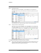
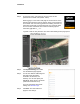
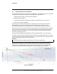
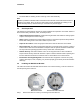
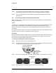
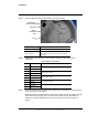
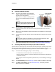
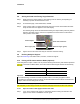
Table Of Contents
- Table of Contents
- Radar Overview
- Installation
- 2.1 Configuring the Radar for Networking
- 2.2 Radar Placement and Orientation
- 2.3 Site Preparation
- 2.4 Installing the Wall Mount Bracket
- 2.5 Connecting the Radar and Installing the Back Box
- 2.6 Installing the Radar Assembly
- 2.7 Uploading a Map Image and Configuring Georeference Settings
- 2.8 Aiming the Radar and Testing Target Detection
- 2.9 Defining Analytics Regions
- 2.10 Pairing a PTZ Camera with the Radar (Optional)
- Operation
- Configuration
- Maintenance and Troubleshooting Tips

427-0101-01-12 Revision 100 September 2020 13
This document does not contain any export-controlled information.
Installation
Step 5 Route the Ethernet cable inside the back box as shown below.
Step 6 (Optional) If you are using the 10-pin connector, terminate cables and plug into
connectors.
10-Pin Power & I/O Connector
Step 7 Secure the back box onto the wall mount bracket using the screwdriver to tighten the three
quarter-turn twist-lock assemblies.
While it is possible to install the wall mount bracket so that the text on the inside of the wall
mount bracket is not upright, when you aim the radar, make sure the THIS SIDE UP
marking on the radar assembly faces up and the FLIR logo on the flat front panel is
upright.
Connector Connection
Ethernet Power and IP communications
10-pin connector
Power and I/O terminal: VAC or VDC power, along with
future release support for alarm I/O and audio I/O (see
table below)
Pin Connection Notes
1VAC/VDC power +
12 VDC/24 VAC optional power when PoE is not available
2VAC/VDC power -
3Alarm Output +
Future release support
4Alarm Output -
5 Alarm Input +
Future release support
6 Alarm Input -
7Audio In +
Future release support
8Audio In -
9Audio Out +
Future release support
10 Audio Out -
Ethernet
10-pin
connector
port
Pin 1
Connector to
radar assembly