
User's Manual


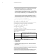


Table Of Contents
- 1 Disclaimers
- 2 Safety information
- 3 Notice to user
- 4 Customer help
- 5 Quick start guide
- 6 Register the camera
- 7 A note about ergonomics
- 8 Camera parts
- 9 Screen elements
- 10 Navigating the menu system
- 11 Handling the camera
- 11.1 Charging the battery
- 11.2 Installing and removing the camera battery
- 11.3 Turning on and turning off the camera
- 11.4 Adjusting the angle of lens
- 11.5 Adjusting the infrared camera focus manually
- 11.6 Autofocusing the infrared camera
- 11.7 Continuous autofocus
- 11.8 Operating the laser distance meter
- 11.9 Measuring areas
- 11.10 Connecting external devices and storage media
- 11.11 Moving files to a computer
- 11.12 Assigning functions to the programmable buttons
- 11.13 Using the camera lamp as a flash
- 11.14 Changing camera lenses
- 11.15 Neck strap
- 11.16 Hand strap
- 12 Saving and working with images
- 13 Working with the image archive
- 14 Achieving a good image
- 15 Working with image modes
- 16 Working with measurement tools
- 17 Working with color alarms and isotherms
- 18 Annotating images
- 19 Programming the camera (time-lapse)
- 20 Recording video clips
- 21 Screening alarm
- 22 Pairing Bluetooth devices
- 23 Configuring Wi-Fi
- 24 Fetching data from external FLIR meters
- 25 Changing settings
- 26 Cleaning the camera
- 27 Technical data
- 27.1 Online field-of-view calculator
- 27.2 Note about technical data
- 27.3 Note about authoritative versions
- 27.4 FLIR T530 24°
- 27.5 FLIR T530 42°
- 27.6 FLIR T530 24° + 14°
- 27.7 FLIR T530 24° + 42°
- 27.8 FLIR T530 24° + 14° & 42°
- 27.9 FLIR T530 42° + 14°
- 27.10 FLIR T540 24°
- 27.11 FLIR T540 42°
- 27.12 FLIR T540 24° + 14°
- 27.13 FLIR T540 24° + 42°
- 27.14 FLIR T540 24° + 14° & 42°
- 27.15 FLIR T540 42° + 14°
- 28 Mechanical drawings
- 29 Application examples
- 30 About FLIR Systems
- 31 Terms, laws, and definitions
- 32 Thermographic measurement techniques
- 33 The secret to a good thermal image
- 34 About calibration
- 34.1 Introduction
- 34.2 Definition—what is calibration?
- 34.3 Camera calibration at FLIR Systems
- 34.4 The differences between a calibration performed by a user and that performed directly at FLIR Systems
- 34.5 Calibration, verification and adjustment
- 34.6 Non-uniformity correction
- 34.7 Thermal image adjustment (thermal tuning)
- 35 History of infrared technology
- 36 Theory of thermography
- 37 The measurement formula
- 38 Emissivity tables

Theory of thermography
36
36.4 Infrared semi-transparent materials
Consider now a non-metallic, semi-transparent body – let us say, in the form of a thick flat
plate of plastic material. When the plate is heated, radiation generated within its volume
must work its way toward the surfaces through the material in which it is partially ab-
sorbed. Moreover, when it arrives at the surface, some of it is reflected back into the inte-
rior. The back-reflected radiation is again partially absorbed, but some of it arrives at the
other surface, through which most of it escapes; part of it is reflected back again.
Although the progressive reflections become weaker and weaker they must all be added
up when the total emittance of the plate is sought. When the resulting geometrical series
is summed, the effective emissivity of a semi-transparent plate is obtained as:
When the plate becomes opaque this formula is reduced to the single formula:
This last relation is a particularly convenient one, because it is often easier to measure
reflectance than to measure emissivity directly.
#T810253; r. AA/42549/42549; en-US
204