
User's Manual


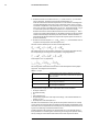


Table Of Contents
- 1 Disclaimers
- 2 Safety information
- 3 Notice to user
- 4 Customer help
- 5 Quick start guide
- 6 Register the camera
- 7 A note about ergonomics
- 8 Camera parts
- 9 Screen elements
- 10 Navigating the menu system
- 11 Handling the camera
- 11.1 Charging the battery
- 11.2 Installing and removing the camera battery
- 11.3 Turning on and turning off the camera
- 11.4 Adjusting the angle of lens
- 11.5 Adjusting the infrared camera focus manually
- 11.6 Autofocusing the infrared camera
- 11.7 Continuous autofocus
- 11.8 Operating the laser distance meter
- 11.9 Measuring areas
- 11.10 Connecting external devices and storage media
- 11.11 Moving files to a computer
- 11.12 Assigning functions to the programmable buttons
- 11.13 Using the camera lamp as a flash
- 11.14 Changing camera lenses
- 11.15 Neck strap
- 11.16 Hand strap
- 12 Saving and working with images
- 13 Working with the image archive
- 14 Achieving a good image
- 15 Working with image modes
- 16 Working with measurement tools
- 17 Working with color alarms and isotherms
- 18 Annotating images
- 19 Programming the camera (time-lapse)
- 20 Recording video clips
- 21 Screening alarm
- 22 Pairing Bluetooth devices
- 23 Configuring Wi-Fi
- 24 Fetching data from external FLIR meters
- 25 Changing settings
- 26 Cleaning the camera
- 27 Technical data
- 27.1 Online field-of-view calculator
- 27.2 Note about technical data
- 27.3 Note about authoritative versions
- 27.4 FLIR T530 24°
- 27.5 FLIR T530 42°
- 27.6 FLIR T530 24° + 14°
- 27.7 FLIR T530 24° + 42°
- 27.8 FLIR T530 24° + 14° & 42°
- 27.9 FLIR T530 42° + 14°
- 27.10 FLIR T540 24°
- 27.11 FLIR T540 42°
- 27.12 FLIR T540 24° + 14°
- 27.13 FLIR T540 24° + 42°
- 27.14 FLIR T540 24° + 14° & 42°
- 27.15 FLIR T540 42° + 14°
- 28 Mechanical drawings
- 29 Application examples
- 30 About FLIR Systems
- 31 Terms, laws, and definitions
- 32 Thermographic measurement techniques
- 33 The secret to a good thermal image
- 34 About calibration
- 34.1 Introduction
- 34.2 Definition—what is calibration?
- 34.3 Camera calibration at FLIR Systems
- 34.4 The differences between a calibration performed by a user and that performed directly at FLIR Systems
- 34.5 Calibration, verification and adjustment
- 34.6 Non-uniformity correction
- 34.7 Thermal image adjustment (thermal tuning)
- 35 History of infrared technology
- 36 Theory of thermography
- 37 The measurement formula
- 38 Emissivity tables

Theory of thermography
36
Figure 36.5 Wilhelm Wien (1864–1928)
The sun (approx. 6 000 K) emits yellow light, peaking at about 0.5 μm in the middle of
the visible light spectrum.
At room temperature (300 K) the peak of radiant emittance lies at 9.7 μm, in the far infra-
red, while at the temperature of liquid nitrogen (77 K) the maximum of the almost insignif-
icant amount of radiant emittance occurs at 38 μm, in the extreme infrared wavelengths.
Figure 36.6 Planckian curves plotted on semi-log scales from 100 K to 1000 K. The dotted line represents
the locus of maximum radiant emittance at each temperature as described by Wien's displacement law. 1:
Spectral radiant emittance (W/cm
2
(μm)); 2: Wavelength (μm).
36.3.3 Stefan-Boltzmann's law
By integrating Planck’s formula from λ = 0 to λ = ∞, we obtain the total radiant emittance
(W
b
) of a blackbody:
This is the Stefan-Boltzmann formula (after Josef Stefan, 1835–1893, and Ludwig Boltz-
mann, 1844–1906), which states that the total emissive power of a blackbody is propor-
tional to the fourth power of its absolute temperature. Graphically, W
b
represents the
area below the Planck curve for a particular temperature. It can be shown that the radiant
emittance in the interval λ = 0 to λ
max
is only 25% of the total, which represents about the
amount of the sun’s radiation which lies inside the visible light spectrum.
#T810253; r. AA/42549/42549; en-US
201