
User's Manual


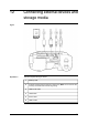


Table Of Contents
- Table of contents
- 1 Warnings & Cautions
- 2 Notice to user
- 3 Customer help
- 4 Documentation updates
- 5 Important note about this manual
- 6 Parts lists
- 7 Quick Start Guide
- 8 A note about ergonomics
- 9 Camera parts
- 10 Screen elements
- 11 Navigating the menu system
- 12 Connecting external devices and storage media
- 13 Pairing Bluetooth devices
- 14 Configuring Wi-Fi
- 15 Handling the camera
- 16 Working with images
- 17 Working with thermal fusion and picture-in-picture image modes
- 18 Working with measurement tools
- 19 Fetching data from external Extech meters
- 20 Working with isotherms
- 21 Annotating images
- 22 Recording video clips
- 23 Changing settings
- 24 Cleaning the camera
- 25 Technical data
- 26 Dimensional drawings
- 26.1 Camera dimensions, front view (1)
- 26.2 Camera dimensions, front view (2)
- 26.3 Camera dimensions, side view (1)
- 26.4 Camera dimensions, side view (2)
- 26.5 Camera dimensions, 41.3 mm/15° lens, side view
- 26.6 Camera dimensions, 24.6 mm/25° lens, side view
- 26.7 Camera dimensions, 13.1 mm/45° lens, side view
- 26.8 Infrared lens (41.3 mm/15°)
- 26.9 Infrared lens (24.6 mm/25°)
- 26.10 Infrared lens (13.1 mm/45°)
- 26.11 Battery (1)
- 26.12 Battery (2)
- 26.13 Battery charger (1)
- 26.14 Battery charger (2)
- 26.15 Battery charger (3)
- 27 Application examples
- 28 Introduction to building thermography
- 28.1 Disclaimer
- 28.2 Important note
- 28.3 Typical field investigations
- 28.3.1 Guidelines
- 28.3.2 About moisture detection
- 28.3.3 Moisture detection (1): Low-slope commercial roofs
- 28.3.4 Moisture detection (2): Commercial & residential façades
- 28.3.5 Moisture detection (3): Decks & balconies
- 28.3.6 Moisture detection (4): Plumbing breaks & leaks
- 28.3.7 Air infiltration
- 28.3.8 Insulation deficiencies
- 28.4 Theory of building science
- 28.4.1 General information
- 28.4.2 The effects of testing and checking
- 28.4.3 Sources of disruption in thermography
- 28.4.4 Surface temperature and air leaks
- 28.4.5 Measuring conditions & measuring season
- 28.4.6 Interpretation of infrared images
- 28.4.7 Humidity & dew point
- 28.4.8 Excerpt from Technical Note ‘Assessing thermal bridging and insulation continuity’ (UK example)
- 29 Introduction to thermographic inspections of electrical installations
- 29.1 Important note
- 29.2 General information
- 29.3 Measurement technique for thermographic inspection of electrical installations
- 29.4 Reporting
- 29.5 Different types of hot spots in electrical installations
- 29.6 Disturbance factors at thermographic inspection of electrical installations
- 29.7 Practical advice for the thermographer
- 30 About FLIR Systems
- 31 Glossary
- 32 Thermographic measurement techniques
- 33 History of infrared technology
- 34 Theory of thermography
- 35 The measurement formula
- 36 Emissivity tables

9.7 Laser pointer
General
The camera has a laser pointer. When the laser pointer is on, you can see a laser
dot above the target.
Figure
This figure shows the difference in position between the laser pointer and the optical
center of the infrared lens:
T638756;a2
WARNING
Do not look directly into the laser beam. The laser beam can cause eye irritation.
NOTE
The symbol is displayed on the screen when the laser pointer is on.
■
■
The laser pointer may not be enabled in all markets.
Laser warning
label
A laser warning label with the following information is attached to the camera:
10743603;a2
Laser rules and
regulations
Wavelength: 635 nm. Maximum output power: 1 mW.
This product complies with 21 CFR 1040.10 and 1040.11 except for deviations pur-
suant to Laser Notice No. 50, dated June 24, 2007.
20 Publ. No. T559598 Rev. a554 – ENGLISH (EN) – September 27, 2011
9 – Camera parts