
User's Manual


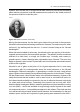


Table Of Contents
- Table of contents
- 1 Warnings & Cautions
- 2 Notice to user
- 3 Customer help
- 4 Documentation updates
- 5 Important note about this manual
- 6 Parts lists
- 7 Quick Start Guide
- 8 A note about ergonomics
- 9 Camera parts
- 10 Screen elements
- 11 Navigating the menu system
- 12 Connecting external devices and storage media
- 13 Pairing Bluetooth devices
- 14 Configuring Wi-Fi
- 15 Handling the camera
- 16 Working with images
- 17 Working with thermal fusion and picture-in-picture image modes
- 18 Working with measurement tools
- 19 Fetching data from external Extech meters
- 20 Working with isotherms
- 21 Annotating images
- 22 Recording video clips
- 23 Changing settings
- 24 Cleaning the camera
- 25 Technical data
- 26 Dimensional drawings
- 26.1 Camera dimensions, front view (1)
- 26.2 Camera dimensions, front view (2)
- 26.3 Camera dimensions, side view (1)
- 26.4 Camera dimensions, side view (2)
- 26.5 Camera dimensions, 41.3 mm/15° lens, side view
- 26.6 Camera dimensions, 24.6 mm/25° lens, side view
- 26.7 Camera dimensions, 13.1 mm/45° lens, side view
- 26.8 Infrared lens (41.3 mm/15°)
- 26.9 Infrared lens (24.6 mm/25°)
- 26.10 Infrared lens (13.1 mm/45°)
- 26.11 Battery (1)
- 26.12 Battery (2)
- 26.13 Battery charger (1)
- 26.14 Battery charger (2)
- 26.15 Battery charger (3)
- 27 Application examples
- 28 Introduction to building thermography
- 28.1 Disclaimer
- 28.2 Important note
- 28.3 Typical field investigations
- 28.3.1 Guidelines
- 28.3.2 About moisture detection
- 28.3.3 Moisture detection (1): Low-slope commercial roofs
- 28.3.4 Moisture detection (2): Commercial & residential façades
- 28.3.5 Moisture detection (3): Decks & balconies
- 28.3.6 Moisture detection (4): Plumbing breaks & leaks
- 28.3.7 Air infiltration
- 28.3.8 Insulation deficiencies
- 28.4 Theory of building science
- 28.4.1 General information
- 28.4.2 The effects of testing and checking
- 28.4.3 Sources of disruption in thermography
- 28.4.4 Surface temperature and air leaks
- 28.4.5 Measuring conditions & measuring season
- 28.4.6 Interpretation of infrared images
- 28.4.7 Humidity & dew point
- 28.4.8 Excerpt from Technical Note ‘Assessing thermal bridging and insulation continuity’ (UK example)
- 29 Introduction to thermographic inspections of electrical installations
- 29.1 Important note
- 29.2 General information
- 29.3 Measurement technique for thermographic inspection of electrical installations
- 29.4 Reporting
- 29.5 Different types of hot spots in electrical installations
- 29.6 Disturbance factors at thermographic inspection of electrical installations
- 29.7 Practical advice for the thermographer
- 30 About FLIR Systems
- 31 Glossary
- 32 Thermographic measurement techniques
- 33 History of infrared technology
- 34 Theory of thermography
- 35 The measurement formula
- 36 Emissivity tables

If the temperature of blackbody radiation increases to more than 525°C (977°F), the
source begins to be visible so that it appears to the eye no longer black. This is the
incipient red heat temperature of the radiator, which then becomes orange or yellow
as the temperature increases further. In fact, the definition of the so-called color
temperature of an object is the temperature to which a blackbody would have to be
heated to have the same appearance.
Now consider three expressions that describe the radiation emitted from a blackbody.
34.3.1 Planck’s law
10399203;a1
Figure 34.3 Max Planck (1858–1947)
Max Planck (1858–1947) was able to describe the spectral distribution of the radiation
from a blackbody by means of the following formula:
where:
Blackbody spectral radiant emittance at wavelength λ.W
λb
Velocity of light = 3 × 10
8
m/sc
Planck’s constant = 6.6 × 10
-34
Joule sec.h
Boltzmann’s constant = 1.4 × 10
-23
Joule/K.k
Absolute temperature (K) of a blackbody.T
Wavelength (μm).λ
178 Publ. No. T559598 Rev. a554 – ENGLISH (EN) – September 27, 2011
34 – Theory of thermography