
User's Manual

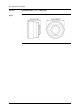
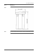
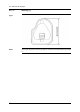
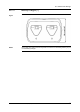
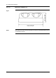

Table Of Contents
- Table of contents
- 1 Warnings & Cautions
- 2 Notice to user
- 3 Customer help
- 4 Documentation updates
- 5 Important note about this manual
- 6 Parts lists
- 7 Quick Start Guide
- 8 A note about ergonomics
- 9 Camera parts
- 10 Screen elements
- 11 Navigating the menu system
- 12 Connecting external devices and storage media
- 13 Pairing Bluetooth devices
- 14 Configuring Wi-Fi
- 15 Handling the camera
- 16 Working with images
- 17 Working with thermal fusion and picture-in-picture image modes
- 18 Working with measurement tools
- 19 Fetching data from external Extech meters
- 20 Working with isotherms
- 21 Annotating images
- 22 Recording video clips
- 23 Changing settings
- 24 Cleaning the camera
- 25 Technical data
- 26 Dimensional drawings
- 26.1 Camera dimensions, front view (1)
- 26.2 Camera dimensions, front view (2)
- 26.3 Camera dimensions, side view (1)
- 26.4 Camera dimensions, side view (2)
- 26.5 Camera dimensions, 41.3 mm/15° lens, side view
- 26.6 Camera dimensions, 24.6 mm/25° lens, side view
- 26.7 Camera dimensions, 13.1 mm/45° lens, side view
- 26.8 Infrared lens (41.3 mm/15°)
- 26.9 Infrared lens (24.6 mm/25°)
- 26.10 Infrared lens (13.1 mm/45°)
- 26.11 Battery (1)
- 26.12 Battery (2)
- 26.13 Battery charger (1)
- 26.14 Battery charger (2)
- 26.15 Battery charger (3)
- 27 Application examples
- 28 Introduction to building thermography
- 28.1 Disclaimer
- 28.2 Important note
- 28.3 Typical field investigations
- 28.3.1 Guidelines
- 28.3.2 About moisture detection
- 28.3.3 Moisture detection (1): Low-slope commercial roofs
- 28.3.4 Moisture detection (2): Commercial & residential façades
- 28.3.5 Moisture detection (3): Decks & balconies
- 28.3.6 Moisture detection (4): Plumbing breaks & leaks
- 28.3.7 Air infiltration
- 28.3.8 Insulation deficiencies
- 28.4 Theory of building science
- 28.4.1 General information
- 28.4.2 The effects of testing and checking
- 28.4.3 Sources of disruption in thermography
- 28.4.4 Surface temperature and air leaks
- 28.4.5 Measuring conditions & measuring season
- 28.4.6 Interpretation of infrared images
- 28.4.7 Humidity & dew point
- 28.4.8 Excerpt from Technical Note ‘Assessing thermal bridging and insulation continuity’ (UK example)
- 29 Introduction to thermographic inspections of electrical installations
- 29.1 Important note
- 29.2 General information
- 29.3 Measurement technique for thermographic inspection of electrical installations
- 29.4 Reporting
- 29.5 Different types of hot spots in electrical installations
- 29.6 Disturbance factors at thermographic inspection of electrical installations
- 29.7 Practical advice for the thermographer
- 30 About FLIR Systems
- 31 Glossary
- 32 Thermographic measurement techniques
- 33 History of infrared technology
- 34 Theory of thermography
- 35 The measurement formula
- 36 Emissivity tables

27.3 Oxidized socket
General
Depending on the type of socket and the environment in which the socket is installed,
oxides may occur on the socket's contact surfaces. These oxides can lead to locally
increased resistance when the socket is loaded, which can be seen in an infrared
image as local temperature increase.
NOTE
A socket’s construction may differ dramatically from one manufacturer to another.
For this reason, different faults in a socket can lead to the same typical appearance
in an infrared image.
Local temperature increase can also result from improper contact between a wire
and socket, or from difference in load.
Figure
The image below shows a series of fuses where one fuse has a raised temperature
on the contact surfaces against the fuse holder. Because of the fuse holder’s blank
metal, the temperature increase is not visible there, while it is visible on the fuse’s
ceramic material.
10739703;a1
88 Publ. No. T559598 Rev. a554 – ENGLISH (EN) – September 27, 2011
27 – Application examples