
User's Manual


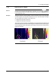
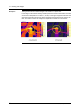

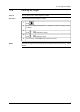
Table Of Contents
- Table of contents
- 1 Warnings & Cautions
- 2 Notice to user
- 3 Customer help
- 4 Documentation updates
- 5 Important note about this manual
- 6 Parts lists
- 7 Quick Start Guide
- 8 Camera parts
- 9 Screen elements
- 10 Navigating the menu system
- 11 Connecting external devices and storage media
- 12 Pairing Bluetooth devices
- 13 Configuring Wi-Fi
- 14 Handling the camera
- 15 Working with images
- 16 Working with thermal fusion and picture-in-picture image modes
- 17 Working with measurement tools
- 18 Fetching data from external Extech meters
- 19 Working with isotherms
- 20 Annotating images
- 21 Recording video clips
- 22 Changing settings
- 23 Cleaning the camera
- 24 Technical data
- 25 Dimensional drawings
- 25.1 Camera dimensions, front view (1)
- 25.2 Camera dimensions, front view (2)
- 25.3 Camera dimensions, side view (1)
- 25.4 Camera dimensions, side view (2)
- 25.5 Camera dimensions, side view (3)
- 25.6 Infrared lens (30 mm/15°)
- 25.7 Infrared lens (10 mm/45°)
- 25.8 Battery (1)
- 25.9 Battery (2)
- 25.10 Battery (3)
- 25.11 Battery charger (1)
- 25.12 Battery charger (2)
- 25.13 Battery charger (3)
- 25.14 Battery charger (4)
- 26 Application examples
- 27 Introduction to building thermography
- 27.1 Disclaimer
- 27.2 Important note
- 27.3 Typical field investigations
- 27.3.1 Guidelines
- 27.3.2 About moisture detection
- 27.3.3 Moisture detection (1): Low-slope commercial roofs
- 27.3.4 Moisture detection (2): Commercial & residential façades
- 27.3.5 Moisture detection (3): Decks & balconies
- 27.3.6 Moisture detection (4): Plumbing breaks & leaks
- 27.3.7 Air infiltration
- 27.3.8 Insulation deficiencies
- 27.4 Theory of building science
- 27.4.1 General information
- 27.4.2 The effects of testing and checking
- 27.4.3 Sources of disruption in thermography
- 27.4.4 Surface temperature and air leaks
- 27.4.5 Measuring conditions & measuring season
- 27.4.6 Interpretation of infrared images
- 27.4.7 Humidity & dew point
- 27.4.8 Excerpt from Technical Note ‘Assessing thermal bridging and insulation continuity’ (UK example)
- 28 Introduction to thermographic inspections of electrical installations
- 28.1 Important note
- 28.2 General information
- 28.3 Measurement technique for thermographic inspection of electrical installations
- 28.4 Reporting
- 28.5 Different types of hot spots in electrical installations
- 28.6 Disturbance factors at thermographic inspection of electrical installations
- 28.7 Practical advice for the thermographer
- 29 About FLIR Systems
- 30 Glossary
- 31 Thermographic measurement techniques
- 32 History of infrared technology
- 33 Theory of thermography
- 34 The measurement formula
- 35 Emissivity tables

15.4 Adjusting an image
General
An image can be adjusted automatically or manually. You use the button
to switch between these two modes. Note that this only works in live mode and not
in preview/archive mode.
Example 1
This figure shows two infrared images of cable connection points. In the left image
a correct analysis of the left cable is difficult to do if you only auto-adjust the image.
You can analyze the left cable in more detail if you
■
change the temperature scale level
■
change the temperature scale span.
The image on the left has been auto-adjusted. In the right image the maximum and
minimum temperature levels have been changed to temperature levels near the object.
On the temperature scale to the right of each image you can see how the temperature
levels were changed.
10577503;a2
Publ. No. T559597 Rev. a554 – ENGLISH (EN) – September 27, 2011 33
15 – Working with images