
User's Manual
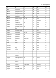
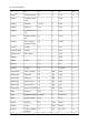


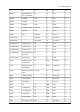


Table Of Contents
- Table of contents
- 1 Warnings & Cautions
- 2 Notice to user
- 3 Customer help
- 4 Documentation updates
- 5 Important note about this manual
- 6 Parts lists
- 7 Quick Start Guide
- 8 Camera parts
- 9 Screen elements
- 10 Navigating the menu system
- 11 Connecting external devices and storage media
- 12 Pairing Bluetooth devices
- 13 Configuring Wi-Fi
- 14 Handling the camera
- 15 Working with images
- 16 Working with thermal fusion and picture-in-picture image modes
- 17 Working with measurement tools
- 18 Fetching data from external Extech meters
- 19 Working with isotherms
- 20 Annotating images
- 21 Recording video clips
- 22 Changing settings
- 23 Cleaning the camera
- 24 Technical data
- 25 Dimensional drawings
- 25.1 Camera dimensions, front view (1)
- 25.2 Camera dimensions, front view (2)
- 25.3 Camera dimensions, side view (1)
- 25.4 Camera dimensions, side view (2)
- 25.5 Camera dimensions, side view (3)
- 25.6 Infrared lens (30 mm/15°)
- 25.7 Infrared lens (10 mm/45°)
- 25.8 Battery (1)
- 25.9 Battery (2)
- 25.10 Battery (3)
- 25.11 Battery charger (1)
- 25.12 Battery charger (2)
- 25.13 Battery charger (3)
- 25.14 Battery charger (4)
- 26 Application examples
- 27 Introduction to building thermography
- 27.1 Disclaimer
- 27.2 Important note
- 27.3 Typical field investigations
- 27.3.1 Guidelines
- 27.3.2 About moisture detection
- 27.3.3 Moisture detection (1): Low-slope commercial roofs
- 27.3.4 Moisture detection (2): Commercial & residential façades
- 27.3.5 Moisture detection (3): Decks & balconies
- 27.3.6 Moisture detection (4): Plumbing breaks & leaks
- 27.3.7 Air infiltration
- 27.3.8 Insulation deficiencies
- 27.4 Theory of building science
- 27.4.1 General information
- 27.4.2 The effects of testing and checking
- 27.4.3 Sources of disruption in thermography
- 27.4.4 Surface temperature and air leaks
- 27.4.5 Measuring conditions & measuring season
- 27.4.6 Interpretation of infrared images
- 27.4.7 Humidity & dew point
- 27.4.8 Excerpt from Technical Note ‘Assessing thermal bridging and insulation continuity’ (UK example)
- 28 Introduction to thermographic inspections of electrical installations
- 28.1 Important note
- 28.2 General information
- 28.3 Measurement technique for thermographic inspection of electrical installations
- 28.4 Reporting
- 28.5 Different types of hot spots in electrical installations
- 28.6 Disturbance factors at thermographic inspection of electrical installations
- 28.7 Practical advice for the thermographer
- 29 About FLIR Systems
- 30 Glossary
- 31 Thermographic measurement techniques
- 32 History of infrared technology
- 33 Theory of thermography
- 34 The measurement formula
- 35 Emissivity tables

654321
20.94T100oil based, average
of 16 colors
Paint
60.95SW20plastic, blackPaint
60.84SW20plastic, whitePaint
90.92–0.94LW704 different colorsPaper
90.68–0.74SW704 different colorsPaper
10.90TblackPaper
10.94Tblack, dullPaper
90.89LW70black, dullPaper
90.86SW70black, dullPaper
10.84Tblue, darkPaper
10.93Tcoated with black
lacquer
Paper
10.85TgreenPaper
10.76TredPaper
10.7–0.9T20whitePaper
90.88–0.90LW70white, 3 different
glosses
Paper
90.76–0.78SW70white, 3 different
glosses
Paper
20.93T20white bondPaper
10.72TyellowPaper
50.86SW17Plaster
60.90SW20plasterboard, un-
treated
Plaster
20.91T20rough coatPlaster
90.91LW70glass fibre lami-
nate (printed circ.
board)
Plastic
90.94SW70glass fibre lami-
nate (printed circ.
board)
Plastic
196 Publ. No. T559597 Rev. a554 – ENGLISH (EN) – September 27, 2011
35 – Emissivity tables